

Ronald Bosley III on Blogger: Driveway Sealing Prospect CT - (203) 819-7414 - VP Asphalt Paving
Ronald Bosley III on Blogger: Driveway Sealing Prospect CT - (203) 819-7414 - VP Asphalt Paving
https://ronaldbosleyiii.blogspot.com/2020/01/driveway-sealing-prospect-ct-203-819.html
Driveway Sealing Prospect CT - (203) 819-7414 - VP Asphalt Paving
Asphalt Driveway Sealing for Residents and Commercial Businesses in Prospect CT 06712
via Ronald Bosley III on Blogger https://ronaldbosleyiii.blogspot.com/

Posted on January 2nd, 2020
Ronald Bosley III on Blogger: Driveway Paving Prospect CT - (203) 819-7414 - VP Asphalt - 06706
Ronald Bosley III on Blogger: Driveway Paving Prospect CT - (203) 819-7414 - VP Asphalt - 06706
https://ronaldbosleyiii.blogspot.com/2020/01/driveway-paving-prospect-ct-203-819.html
Driveway Paving Prospect CT - (203) 819-7414 - VP Asphalt - 06706
Affordable Asphalt Driveway Paving in Prospect, Connecticut for 2020 and Beyond...
via Ronald Bosley III on Blogger https://ronaldbosleyiii.blogspot.com/
Posted on January 1st, 2020
Ronald Bosley III on Blogger: Installing Shop Fans – Big Ass Fans
Ronald Bosley III on Blogger: Installing Shop Fans – Big Ass Fans
https://ronaldbosleyiii.blogspot.com/2018/12/installing-shop-fans-big-ass-fans.html
Installing Shop Fans – Big Ass Fans
With it coming up on the holidays, things are winding down for me in the shop. I’ll be taking off a little bit of time to regroup from my extremely busy year and spend time with family…..It occurred to me earlier today that I built a 4,000 sqft shop this year, which is just incredable. It seems like it was so long ago. 2018 has been outstanding and I hope you’ve enjoyed coming along with me this year as I tackled a large assortment of projects. I wish you all a very Merry Christmas and a Happy New Year. But one last video for the year. As I was looking through footage I realized I installed fans earlier this summer in the shop but never released the video covering the process. So lets jump into it.
Fans I installed:
I installed two different kinds, inside the shop I installed a giant Big Ass Fan in the center of my woodworking space and four smaller Hakui fans on the covered porch.
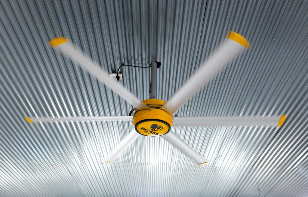

If you aren’t familiar with the Big Ass Fan brand, they make crazy efficient and stunning looking equipment. If you watched the shop build you’ll remember that I installed their lights. Since I wanted to place this 7’ diameter fan in the center of my woodworking space, I first started by taking out the light that marked center of my ceiling then also removing a few ceiling panels where the fan would need to go.

This size of fan requires a mount to be fabricated that will span across the bottom cord of two trusses which is why I’m having to take down the ceiling panels to expose the bones. If you don’t want or require such a large fan there are models that will allow you to attach the fan to one truss which would mean you wouldn’t have to expose the trusses.
I fabricated my mount from two pieces of angle iron backed up to one another. I first cut them to the length needed to span two trusses then joined them together by drilling a hole dead center for a nut and bolt, using my Triton Super Jaws and a pair of vise grips to hold them in place for me. I repeated the steps in order to make two brackets at the same time.


After getting those punched I moved the pieces down to the ground, separated them, and drilled two holes on the flat portion that will be sitting on the truss.


With those together now I grabbed the hardware that will attach to these mounts in order to hang the fan from. I positioned it in center and marked the location of the holes that needed to be drilled out. When punching through metal I always work up to the final size hole if it’s somewhat large. So for these I start off with punching a 1/4” hole, then step up to the final 1/2” size which is the bolt I’m using.


Once I got those tighter I ran the wiring through the center tube for the electrical bits then dropped that down in the center of the mount. Now it was ready to set into place. To keep it from moving I temporarily clamped it in place while I crawled up top and attached it with lags to the bottom cord of the trusses.


Something I really love about this fan is the wall mounted remote, it’s more of a speed indicator as it not only turns the fan off and on but also dictates how fast or slow it spins.

I didn’t want to run the wiring on the outside of my ceiling material so that meant I had to crawl up into the attic….let me remind you this during the heat of summer!….and get into the tiny tiny point on the far side of the roof in order to feed down the wire to Brian. My recommendation is if you are building a shop, even if you don’t install fans at the start, leave yourself a wire from where you’ll eventually want the controller to the placement of the fan. Just coil it up and leave it in the attic so you don’t have to do all this crawling around.
Alright, next up was mounting the motor into place, which might take two people because it’s pretty heavy.


Next up was mounting the airfoils. These do come in different diameters but mine are 3’ long, which including the center hub span, makes this fan 7’ total. And let me tell you….it’s crazy how much air this fan can move, and also how still and quiet it is. Even when I crank it up all the way you don’t hear any sounds from it other than the air itself moving.


And that’s it for the installation part of the big fan, so next was throwing back up the ceiling panels that were taken down earlier. To get around the fan’s stem I used a rotary tool to make a cut around it.

While I was mounting fans, next I moved to the porch. I love working on my covered shop porch when the weather is nice enough so having the option to get some moving air out there was a must for me. For this area I’m going with a smaller Big Ass Fan called Haniku. These fans have over 1000 options for finishing combinations but I went with Carmel and Black to match the cedar beams I have on the porch.

These fans are ultra quick to assemble. It was honestly as simple as attaching the fan blades, attaching the center tube with the wiring in it, then adding both hubs that keeps the top and bottom ends of the tube looking nice once it’s mounted. 

Haiku has won more than 75 international design and technology awards and one thing they strive for and hit, is ensuring their fans don’t wobble. I found out they have a 13 step process to hand balance each fan so you won’t have to be distracted by the repeated off balance rhythm so many fans make.


After I mounted the bracket on the ceiling where I wanted the fan, I placed the ball into the socket, that’s what I’m describing it as at least, and turned it on. These fans also come with a remote and allow you to control the speed. Ha we were laughing because there is an actual “whoosh” button : )

Also, big high five on not only the quality of the fans, but also the instructions, and even making the remote magnetic. Just from head to toe, from aesthetics to function, everything on these products screens thought, effort, and quality.
If you’re looking at mounting fans in the shop or even in your house I can’t recommend these enough. They are highly efficient, exceeding the Energy Star requirements for ceiling fans, extremely quiet, and have a customizable look for every space.
If you’d like some of your own, check out the Big Ass Fan website here.
And while you’re checking things out, check out April Wilkerson merch here.
Ok, that’s it for 2018! Not only was I able to build my shop this year, I was able to put a big dent in my to-do list for outfitting and personalizing it. And that’s a great feeling. Thanks for coming along.
I’ll see you in 2019.
The post Installing Shop Fans – Big Ass Fans appeared first on Wilker Do's.
from Wilker Do's http://bit.ly/2Sq84dA
via Ronald Bosley III on Blogger http://bit.ly/2RdAsSO
Posted on December 27th, 2018
Ronald Bosley III on Blogger: Asphalt Maintenance is Key to Happy Customers in 2019!
Ronald Bosley III on Blogger: Asphalt Maintenance is Key to Happy Customers in 2019!
https://ronaldbosleyiii.blogspot.com/2018/12/asphalt-maintenance-is-key-to-happy.html
Asphalt Maintenance is Key to Happy Customers in 2019!
Winter can cause major damage to your parking lots or driveways. Don’t lose customers due to potholes and cracks in your asphalt. The team at Asphalt Pavement Solutions is now booking commercial clients for 2019. We offer services such as crack sealing, car stops, bollards, line striping, asphalt and large parking lot pothole repairs in…
The post Asphalt Maintenance is Key to Happy Customers in 2019! appeared first on Asphalt Pavement Solutions.
from Asphalt Pavement Solutions http://bit.ly/2PTVNMr
via Ronald Bosley III on Blogger http://bit.ly/2RdAsSO
Posted on December 21st, 2018
Ronald Bosley III on Blogger: DIY Insulated Dog House
Ronald Bosley III on Blogger: DIY Insulated Dog House
https://ronaldbosleyiii.blogspot.com/2018/12/diy-insulated-dog-house.html
DIY Insulated Dog House
Things I Used in This Project:
ISOtunes Bluetooth Hearing Protection
Titebond III Wood Glue
Miter Saw Stand Plan
Miter Saw
Infinity Table Saw Blade
Infinity Miter Saw Blade
Woodpeckers Speed Square
Armor Tool Pocket Hole Jig
Woodpeckers Straight Edge
Woodpeckers 12″ Square
Triton Track Saw
Brad Nailer
Titebond Thick and Quick
When my dogs aren’t with me in the shop, they are hanging out on the wrap around porch which has plenty of shade, is out of the rain, and always has a great breeze. During the summer it’s awesome because they stay cool but during the winter it’s hard for them to get warm. So this week I built them a dog house with the purpose of giving all three of them a place to get away from the wind and snuggle up. Let me show you how I did it.
This will be an insulted dog house so instead of going with my first instinct which was a plywood body, I went with more of a framing design made from 2x4s ripped in half. I first sent the 2x4s through my table saw to take off the rounded edges on both sides, then readjusted the fence and cut them directly in half.

After getting them cut to width I then cut everything to length at the miter saw.

I started by constructing what will be the two sides, coming up a few inches on a few pieces to give the house some small feet and get it up off the ground. Again, mine will be under a porch and should be kept dry but just incase.
I’ll be using pocket holes to join things together and I’m very excited to introduce a new jig to hit the market that has some really great features.It’s the Armol Toos Pocket Hole Jig. Right off the bat they made the deck of the jig the same height as a 2×4 so it’s easy to create side support feeds. Of course I don’t need them in this instant but this will come in handy. So on a traditional pocket hole jig you have three things to adjust, the drill block, the clamping tension, and the drill bit collar….on this jig all of those things are self adjusting so all you have to do is stick in your material. If you want to go from 1 1/2” to 3/4” you just clamp the new material into place and you see everything automatically adjusts for you. You can use the onboard Allen key to tighten down on the drill bit collar then you’re ready to go. If you want to double check, there are indication markings on the side annnnd they are color coordinated to the length of screw you need for that thickness of material. Pretty sweet if you ask me.


After getting all the pocket holes drilled, I started attaching things. Even though this house shouldn’t ever see moisture it will be outside so I went ahead and used Titebond III wood glue since it’s a waterproof glue.

After getting one side assembled, I repeated the process to create another. Next I started working on the front panel, first cutting everything to size, drilling in pocket holes, then gluing and screwing it in place. This design is very easy to adjust depending on your size of dog. Since I have three and they all like to snuggle up together, I made this one long enough to fit three of their beds but still give them room to get around one another.

After getting the door in place, I thought I should double check to see if they could comfortably fit. With that test passed, I moved on to attaching the back panel. Moving things to the floor to have more working room.


Next up was a floor, but before putting in the decking material I threw in some insulation. This comes in a big 4×8 sheet and is 3/4” thick. Since my framing is 1 1/2” thick I cut two panels per opening and doubled filled up the cavity. I would use a straight edge and a box blade or my pocket knife to cut it out, then stuck it in place.


Once the bottom was full I measured and cut some plywood to deck it. I ended up cutting this piece in half to make getting it into place a little easier and I just made sure to cut it in the center so I could join the seam to the floor joist.

And now more insulation for the walls! To make this step easier I would cheat and set the panel directly on top of the foam then just trace the shape I was needing. If you’re working alone, you can set the insulation on the floor so you have less travel distance to move the entire house. I would line one of the straight edges up to the edge of the insulation then trace the rest, cut it then stick it in place. I was originally thinking I would need to glue these panels in place but the friction fit was so snug I skipped the glue all together. Oh and just a reminder this insulation has foil backing on both sides so if you want to use your table saw to cut it down, and have a SawStop then just be sure to put it in bypass mode or it will tip right away.

The set in place and tracing method worked so well I next repeated it for the siding! For the siding I’m going with beadboard. This stuff is a huge pain to paint but it does give it some good texture and it’s pretty lightweight, only being 3/8” thick. As you can see I dragged the full sheet over to my work area, then set flipped around the house in order to trace all the sides. If you do this of course just make sure a horizontal reference is squared up to the headboard so your panel doesn’t come out wonky looking.

After getting the sides traced I used my tracksaw to cut all the shapes out then Titebond III and brad nails to stick it in place. I started by attaching the two side panels so that when I cut and attached the front and back, the edges of the side panels would be covered up.


On the front panel, I went ahead and covered up the opening to the dog house with the bead board, but then after getting it secured in place I used a large drill bit to punch a hole through. Then I used a router and a flush trim bit to perfectly cut out the opening. If you don’t have a router then you can also use a jigsaw or even a reciprocating saw to do this.

Now moving on to the roof. Since the dog opening is muuuuch smaller than me, I wanted to make the roof into an access panel to the inside so I decided to make it hinged. This will allow me to easily grab the beds to wash, check for snacks, or anything else. I decided to use the left over beadboard I had from the siding to create this roof and also decided to split it into two doors instead of just a single. This is fine for mine since it will live under a covered porch but if you plan to place your house in the rain then keep it as a single panel so rain won’t drip through the seam.

Before attaching things, I set the roof panels aside and gave everything a coat of paint. Like I said before, beadboard is not fun to paint because it takes two forms of application. I would first use a roller to get all the flat surfaces, but then used a brush to get into all the valleys. Looking back on it, I should have used my sprayer, that would have saved me a ton of time, but oh well. For the body I am going with a grey and while it was drying, I also grabbed what will be the trim boards and threw a coat of paint onto them as well to be drying. Instead of white, I’m going with a light grey.

While those were drying, I started attaching the roof panels. I started by centering and squaring up the panels to the body. Once I had it just so, I used a pencil to trace the underside of the panels. This line indicates the outside of the body, but since I want to also insulate the roof I needed to know where the inside of the body fell on these panels. With the framing being 1 1/2” thick, I grab something that was 2” thick, which just happened to be a level, and used this to mark the inside line. Now that I had this reference I could measure the area inside and cut a piece of insulation to size. To attach these panels Im’ using a multi surface glue made by Titebond called Thick and Quick. Since I could use brads to hold it in place while that dried, I grabbed an assortment of tools and just weighted it down for a bit.


While that was setting up to dry I started working on the trim. I ripped down my 1x boards I had painted earlier then started cutting them to length and attaching them. Glue doesn’t stick very well to painted surfaces so learn from my mistake and leave the top edge of your body unpainted to give you a clean surface to glue to.

I’m again starting on the edges of the house so that the front and back trim will cover up the end grain of the side trim. I also always cheat on trim. Instead of measuring and cutting I typically just hold the board in place and mark the back side.

By this time the insulation was well past stuck in place so I first attached a portion of paino hinge to the underside then crawled inside the house and attached it to the body. And I should have seen it coming but to be honest I didn’t think about it when I was working the design….but the door actually has a built in stop with the overhang on the back end. So that’s convient. : )

Nice, that works nicely. After getting one secure, I repeated on the second. I used the Tounge and groove feature of the beadboard to make the seam in the middle disappear. This is great except when I tried to lift up one without the other, it was running into each other and prevented it. To fix this issue I grabbed my multi tool and just notched out a small portion in the back so that I could open one and give it clearance to pass up the other. There we go, now it’s working correctly.

Next I did all the finish painting to the inside, the underside of the roof, and any other exposed wood. Now when I was trimming around the door I left the top piece of trim long so I could hang something cute and special. I used my CNC machine to cut out a cut little paw print and instead of just glueing this to the side, I instead added a small hook to the overhung trim and the paw so that I could hang it and there would be a slight swing to it. Hehe, I think the dogs will appreciate the marking.


I thought I was done but the roof was really bothering me with how thin it looked compared to everything else. So I ended up ripping some 1/2” plywood and adding a small strip around the primereter of the underside of the roof. This just bulks up the look some and I think makes it looks better.

And that’s it! Now the pups have a place they can crawl inside to get out of the wind that’s always present on our hill. They can all be together which will make them happy, but still have room to get around one another. Also, I have a way to peak in at them to make sure they aren’t staying up late and ordering pizza.


So a few followers on my Instagram page were mentioning their dogs would tear up the exposed insulation on the inside. Mine don’t chew or scratch things up, but if yours do then I would certainly recommend adding a layer of thin sheeting to the inside as well. Don’t forget I have a set of plans for this build in the plans section of this website.
That’s it for this one, I hope you enjoyed it.
The post DIY Insulated Dog House appeared first on Wilker Do's.
from Wilker Do's https://ift.tt/2CnUOQU
via Ronald Bosley III on Blogger https://ift.tt/2MdONsZ
Posted on December 19th, 2018
Ronald Bosley III on Blogger: Building Swing Out Stools 3 Legged Stools
Posted on December 12th, 2018
Ronald Bosley III on Blogger: Building Custom Stool Seats from Scrap Wood
Ronald Bosley III on Blogger: Building Custom Stool Seats from Scrap Wood
https://ronaldbosleyiii.blogspot.com/2018/12/building-custom-stool-seats-from-scrap.html
Building Custom Stool Seats from Scrap Wood
Things I Used in This Project:
ISOtunes Bluetooth Hearing Protection
Ultimiate Workbench Plans
CrossCut Sled
Titebond Original Wood Glue
Rockler Surefoot Clamps
Triton Router
Infinity Spiral Bit
Carpet Tape
Triton SuperJaws
Large Compass
Large ROS
Palm ROS
Triton Router Table
Infinity Round Over Bit
Infinity Chamfer Bit
Push Blocks
Bench Cookies
Dust Collection Cart
RIDGID Round Shop Vac
Universal Small Port Hose Kit
Dust Right Separator
Wipe On Poly
These seats are actually something I’ve been wanting to tackle for a while. They are inspired by a fabulous NY based furniture maker named Ethan Abramson. He has these stools he builds that he calls Maze Stools, that are made from different woods and have a very random yet elegant look to them. With Matt Cremona and I only having a single day to knock something out, I figured it was the perfect project. I also thought it would be cool to incorporate a scrap from Matt’s shop so I told him to toss something into his suitcase for me. Of course, it being Matt he brought me a beautiful piece of airdried walnut that he milled himself.


To get started we rounded up some other cut off of hardwoods from my lumber rack. I had two good chunks of walnut then found some maple and Matt found some small pieces of curley maple. We divided them up then started playing with our designs. The great thing about this project is there is no right or wrong, mine is pretty simple whereas Matt went a little crazier with his, even throwing some end grain into the mix.

Since we are dealing with scraps, almost all the boards are different thicknesses. Later we will plane our seats down but right now I just got the boards close by resawing them at the bandsaw.
I was aiming for my seat to be around 14” so while I was building up mine I would use a tape just to make sure I was getting the weigh and height needed on the initial build up. Once that looked good, I started playing with adding more to the design. I wanted a strip of maple across the top so I grab a thinner strip, placed it where it looked good and used a pencil to mark on the bottom walnut, it’s location. Then I took it over to the table saw and cut along these pencil marks. This allowed to insert the maple strip where I removed the material.

With the general arrangement of our seats figured out, we started on the first glue up. Since I don’t yet have a jointer, we used my crosscut sled at the table saw to get the glueing edges nice and flat then started clamping things together. This part is a little funky because lots of things are cut at angles so they want to slip and slide once you start applying pressure with the clamps. But! We both played with it enough and got things to hold together.


After letting that set for an hour or so, we unclamped our pieces and started cleaning up the edges for round two. On mine, I just cut the left side flush so I could add another board Maple to the edge. Then Matt cut his slides flush to add more walnut and curley maple to both sides.

After letting round two glue ups dry, Matt attached the adjustable circle cutting router base to the router, then we turned these funky little creations into circles. You can see we placed a spoil board below the seat just to protect my new workbench top, then used carpet tape which is a strong double sided tape, to hold down the seat. Matt’s glue up was a tad bit smaller than mine so he went with a smaller diameter for his seat. We used a spiral upcut bit made by Infinity to make this cut, and since it’s pretty thick we took three passes to cut all the way though.

One tip to remember if you do this project is to attach your seat upside down, so that what will end up being the top of the seat is facing the workbench. This will make the screw hole from attaching the router in the bottom where it will be unseen instead of the top.
With that done, next we moved the seats and the SuperJaws outside because next step was to dish out the seat some. For this we were using my power carvers with the sanding attachment on them. To give a visual reference to follow, we used a compass to pencil on an offset line then just started sanding away material.

And I’m curious on what other methods there are for dishing out seats that might be quicker. Although this process wasn’t too bad. Matt only took about 15 mins to get his dished, then enjoyed the nice Texas weather while I took a little bit longer to complete mine.
Anyways, back to the project…..next we cleaned up the dish and also the edges with the palm ros sander. Or well, I used the sander, Matt used the spokeshave. Which I think proves power tools and hand tools can be friends. Just sayin….

Before applying finished, we took our seats over to the router table and used a 1/2” round over bit to round off the top edge. This not only looks a little nicer but will also make it feel nicer on the back of the legs when actually using the seat. Then something I did on mine is I placed a small chamfer on the bottom edge of the seat.

After he signed the bottom, he applied two coats of Danish oil. And my goodness that’s pretty.

Matt and I actually made these back in August and two seats is just not enough for my shop. So I decided to make some more, but I loved the concept of including scraps from friends and having a piece of them in the shop. So for the past few months, if I knew I would be seeing a friend, I would tell them to toss a scrap into their luggage for me and I’ve come away with quite the haul. I ended up with enough to make at least six more stools so that’s what I did.

I mixed and match the pieces to get a modge podge sort of look, but I also tried to maintain good aestics with color coordinating. One thing I didn’t pay any mind to is grain direction. Wood of course expands and contracts so typically you want to keep the grain all going the same way so it moves together and doesn’t bust apart, but these pieces are so small I don’t think it will create an issue. But hey, we’ll see. The two Matt and I made this summer are still looking perfect if that’s any indication.

Something I made this go round to help with visualizing is a cardboard cutout. I used 14” as a template then could place this ring over my working piece to see if I liked the direction it was going or where on the board I wanted the circle placed.

You can see that I placed a small sheet of wax paper under each one of my glue ups, this is just to keep me from gluing it down to my workbench. : ) Each seat had at least two glue ups, if not three but since I was building so many I was easily able to keep busy making another while things were drying.
Of course this is a really great project to use up some smaller scraps but I think this would be a really fun group project. Call up some woodworker friends, everybody bring one or two pieces of wood and gather in somebody’s shop (whoever has the most clamps) then spend the day building a seat for your space while enjoying friends company then everybody gets to leave with a momento that’s useable.
It’s really cool to look them all at the end and see just how varied each one can be. It’s also funny to see what they look like after all the glue ups….at this point I was thinking “hmmmm, these are funky to say the least”. But I will tell you that after cutting them down into a circle, they look muuuuuch better.

Now since I had so many, I used double sided tape to temporarily secure all of them down to my workbench and this made going over each one with my sander a little bit quicker rather than placing them one by one into my SuperJaws.

Next up, will be making some bases to go with these tops. I have a pretty fun idea I can’t wait to try out, so stay tuned for my next video to see them complete. Big thank you to my friends and viewers who contributed a scrap for these seats.
The post Building Custom Stool Seats from Scrap Wood appeared first on Wilker Do's.
from Wilker Do's https://ift.tt/2rsQrh7
via Ronald Bosley III on Blogger https://ift.tt/2MdONsZ
Posted on December 9th, 2018
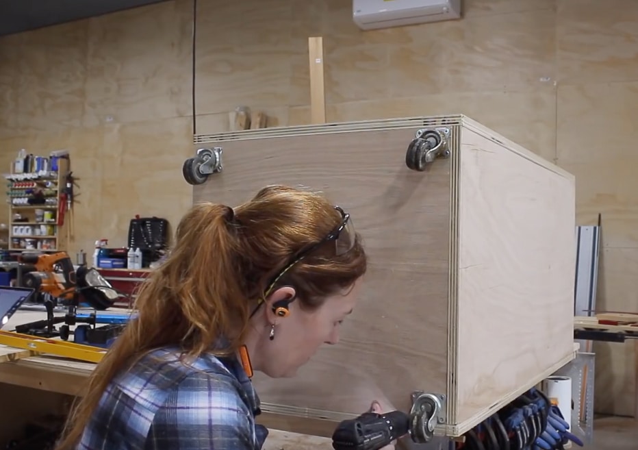
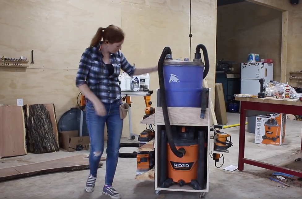
Ronald Bosley III on Blogger: Dust Collection Cart – Shop Vac and Separator Storage
Ronald Bosley III on Blogger: Dust Collection Cart – Shop Vac and Separator Storage
https://ronaldbosleyiii.blogspot.com/2018/11/dust-collection-cart-shop-vac-and.html
Dust Collection Cart – Shop Vac and Separator Storage
Toting around my shop vac and my separator anytime I want to use dust collection with my power tools is such a pain, so this week I built this cart to simplify things for me.
Things I Used in This Project:
RIDGID Round Shop Vac
RIDGID Square Shop Vac:
Dust Right Separator
ISOtunes Bluetooth Hearing Protection
Universal Small Port Hose Kit
Sketch Up
Hercules Dolly
Ultimiate Workbench Plans
Triton Track Saw
Cord Reels
Right Angle Clamp It Jigs
Titebond Original Wood Glue
Woodpeckers 12″ Square
Rockler Surefoot Clamps
Infinity Table Saw Blade
Infinity Insert Plate
4″ Belt Sander
3″ Belt Sander
Palm Belt Sander
Large ROS
Palm ROS
Sand Paper Cutter
If you’re new to this hobby then a quick overview for you is: breathing in dust is bad. One way to control it is to hook a shop vac directly to your tool when you’re using it. This sends all the dust through the filter of the shop vac and the shop vac collects it.
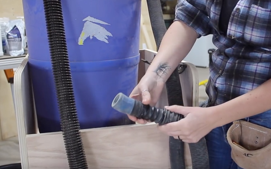
A great add on to this set up is a cyclone or a separator. I have the Dust Right Separator where I hook up a hose to my tool that feeds into the separator, then the separator feeds into the shop vac. This separator collects the majority of the saw dust that I create, leaving only the finer saw dust to go through the filter of the vac and be collected.
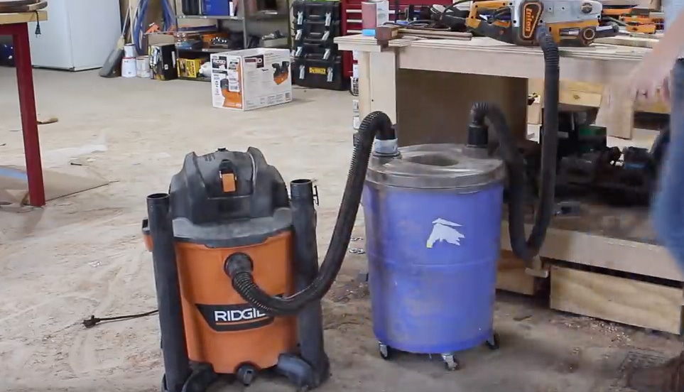

This is my preferred set up. However, getting back to the irritation, it’s a pain to haul both of these individual units around the shop to where I’m working. So this week I designed a storage solution to simplify it.
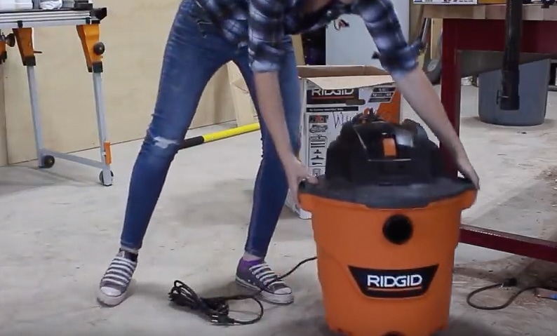
I decided to go ahead and upgrade my shop vac while I was building something. I’ll be using a RIDGID 12 gallon 5hp wet/dry vac. It’s pretty much the same height as my separator.
I played around with designs and decided to make a taller cart than I originally planned, with a smaller footprint. This is an option with the units stacked, with the hose going straight out from the vac up to the separator. I still had room for the sanders on the left and the ROS’s on the right, but then broke up the sandpaper storage to go on both sides in order to make it all fit.
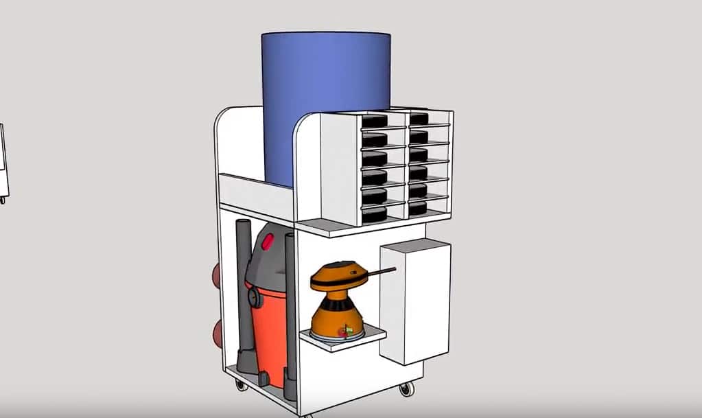
Having these design changes and options is exactly why I love taking the time to model my projects before starting. Ok now that you see what I’m going after, lets build it.
I’m building it from one sheet of 3/4” plywood so I started by wheeling a sheet over to my workbench and breaking it down with my track saw.

Once I had things at a more manageable size, I took those sheets over to the table saw and broke them down to their final size. And just a tip for you: whenever I’m working off a cultist, after I cut a piece to size I label the edge so I won’t get it mixed up with the other parts of the build.
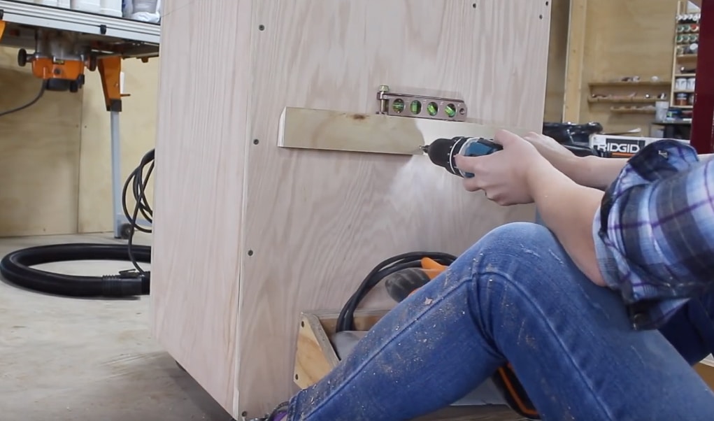
To start joining things together I grabbed the back and one of the sides then used the aid of these right angle clamp it jigs to hold both together at a 90. This makes it easy to go through and predrill then attach with screws. After getting one side attached, I repeated the process for the other side.

Next I flipped it on it’s back and attached the bottom. Oh and I’m using Titebond original for this project. Next I attached the shelf in the same manner. I first measured on where it needed to go then made marks on the front and back on both the side pieces. Before securing it with screws, I also use a square just to make sure everything looked good. Once I had the two front corners pinned, I used the square to draw a line down center so I could pre drill and screw the back of the shelf into place. After repeating on the other side, I quickly attached four casters to the bottom to make this unit mobile, then set it on the ground to test out.


Separator goes on top, shop vac on bottom. The hose as well as all the attachments have a quick connect feature which will make not only connecting the hose but also disconnecting it to clean out the vac, quick and easy.
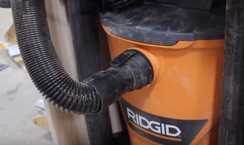
I thought I would have to build in some holders to store the vac attachments but RIDGID actually incorporated a storage method in the feet! So that’s handy and saves me a step.

Now the reason the separator is on the top is because it’s the portion that is connected to my power tool and I wanted it to have the ability for it to pivot around along with me instead of being confined inside the lower cubby. That’s also the reason I left it on casters. To keep it from falling off the shelf however, I placed a front lip in between the two sides. And you can see that if this end is connected to my tool, I can go pretty much anywhere and the separator will rotate around with me instead of me having to rotate the cart.
The shop vac comes with these handy hose holders with the intention of giving you an onboard place to store it away when you aren’t using it. However, since it isn’t needed on the vac in my case, I repurposed them to hold my smaller hose from the separator instead of just tossing it inside the top compartment. This will keep the hose conveniently placed for easy grab and use.

I’m not incorporating any extra hose storage on my unit because I use this Rockler small port hose kit….which is a flex hose that is a stock diameter but comes with thread-on connections that are interchangeable. So instead of swapping out the entire hose to fit different ports on my tools, I just switch out the thread ons.
Ok let me pause and explain my thinking for this next part: I most often pull out the shop vac and separator when I’m running one of my five sanders and in most projects I never just use one. Instead of making lots of trips to grab my sanders from my French cleat tool wall, then having to put them back, I decided to place all my sanders on this cart. So that’s what I did next. Since I already built holders for these tools it was as simple as grabbing them off my wall and placing a cleat on the side of the cart.

My buddy Jay Bates built a similar cart for a vac and separator a few years ago but he went with a much lower profile body. So if you aren’t interested in all the side storage then I recommend checking out his plan here.
Since I’m storing my sanders, I also wanted to keep some sort of sandpaper storage here. I grabbed a piece of 3/4″ plywood that was wide enough to make up both of my sides. I then changed out my dado stack for a 1/4″ stack and cut a bunch of grooves. After getting those cut, I changed back my blade to a single black and cut this board in two down the middle in order to create the two sides needed.
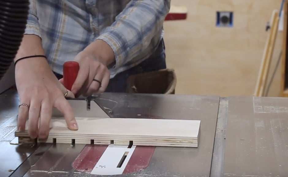
With the body done, I grabbed some 1/4″ scrap material, cut it to size and then glued them in place to make the shelves. After the glue dried, I did some sanding and then hung the sandpaper storage up. Instead of a French cleat on this one, I opted for pocket holes to keep the profile slim.


I was about ready to call this project done when I stumbled across a sandpaper cutter made by Rockler that I thought was so cool. So I put it up on my cart as well, next to my flat sandpaper. Now whenever I have a sheet of flat paper that needs to be torn to size for my sanding blocks, all I have to do is stick it into the holder, line up the side of the paper to the depth gauge, and then just rip it.

The last thing I included was a power strip. I originally wasn’t going to, I was just going to drill a hole in the back of the unit for the plug of the shop vac to pass through. However, I liked the idea of plugging the power strip into my cord reel, then being able to plug any of my sanders into the power strip instead of also having to run them to my cord reel. So main power comes in here, then I have plenty of outlets to run the tools that are being used with the shop vac cart.


This cart definitely simplifies moving both of these units around.
That’s it for this one. I hope this project helps you out. See you on the next build.

Find me on Patreon: https://ift.tt/2njTR2y
Follow me on Instagram: https://ift.tt/1QZ44xP
The post Dust Collection Cart – Shop Vac and Separator Storage appeared first on Wilker Do's.
from Wilker Do's https://ift.tt/2DQRm2h
via Ronald Bosley III on Blogger https://ift.tt/2MdONsZ
Posted on November 29th, 2018
Ronald Bosley III on Blogger: Business Owners, Fall Is the Season for Commercial Asphalt Repair!
Ronald Bosley III on Blogger: Business Owners, Fall Is the Season for Commercial Asphalt Repair!
https://ronaldbosleyiii.blogspot.com/2018/11/business-owners-fall-is-season-for.html
Business Owners, Fall Is the Season for Commercial Asphalt Repair!
Now that summer is behind us, and the region is beginning to prepare for the winter ahead, asphalt maintenance companies in Camden County and the surrounding areas are beginning to schedule commercial asphalt repairs before the harsh winter weather arrives. For property owners across the Northeast, winter weather can cause a variety of problems. When…
The post Business Owners, Fall Is the Season for Commercial Asphalt Repair! appeared first on Asphalt Pavement Solutions.
from Asphalt Pavement Solutions https://ift.tt/2Fxdx0d
via Ronald Bosley III on Blogger https://ift.tt/2MdONsZ
Posted on November 19th, 2018
Ronald Bosley III on Blogger: 4 Shop Organizing Projects
Ronald Bosley III on Blogger: 4 Shop Organizing Projects
https://ronaldbosleyiii.blogspot.com/2018/11/4-shop-organizing-projects.html
4 Shop Organizing Projects
In my shop this week it was all about doing a little bit more organizing. I’m sure you know it’s easy to set a pile on the floor and let it continue to live there. So I find that by forcing myself to look at it and think “what do I want to do with this”…little bit by little bit I’m slowing breaking in my shop and making things easier to find.
Things I Used in This Project:
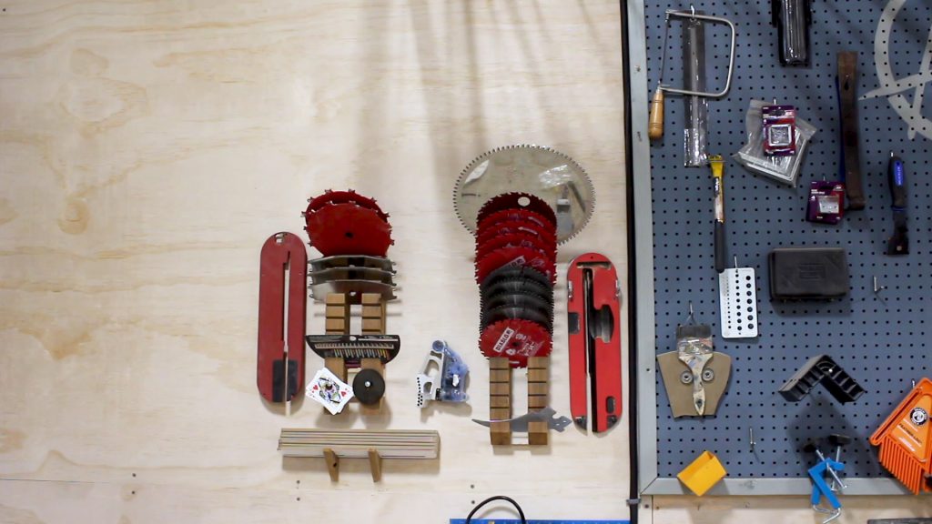
Let’s start off with a storage solution for extra saw blades and all those accessories. Between my track saw, circular saw, miter saw, table saw… and then I also have my dado stack, insert plates and all of the interchangeable inserts. I’ve had a big pile sitting on the floor next to my table for a while.

As I often do with shop project, I looked through my scrap wood and found chuck of cedar that will work well for this project. I started off by marking down one edge every 1”. Then I set my table saw to 45 degrees and made the cuts line up to my marks.


After working down the entire length of board I set my saw back to 90 and ripped it right down the middle.

I placed a French cleat on the back as well as on the wall then started loading it down with my blades. Starting off with my larger diameter blades at the top. I made an identical one for my dado stack.


For my insert plates I cut two triangles at the bandsaw, drilled a pocket hole into each, then attached them to the wall to create a shelf I could set the inserts on.
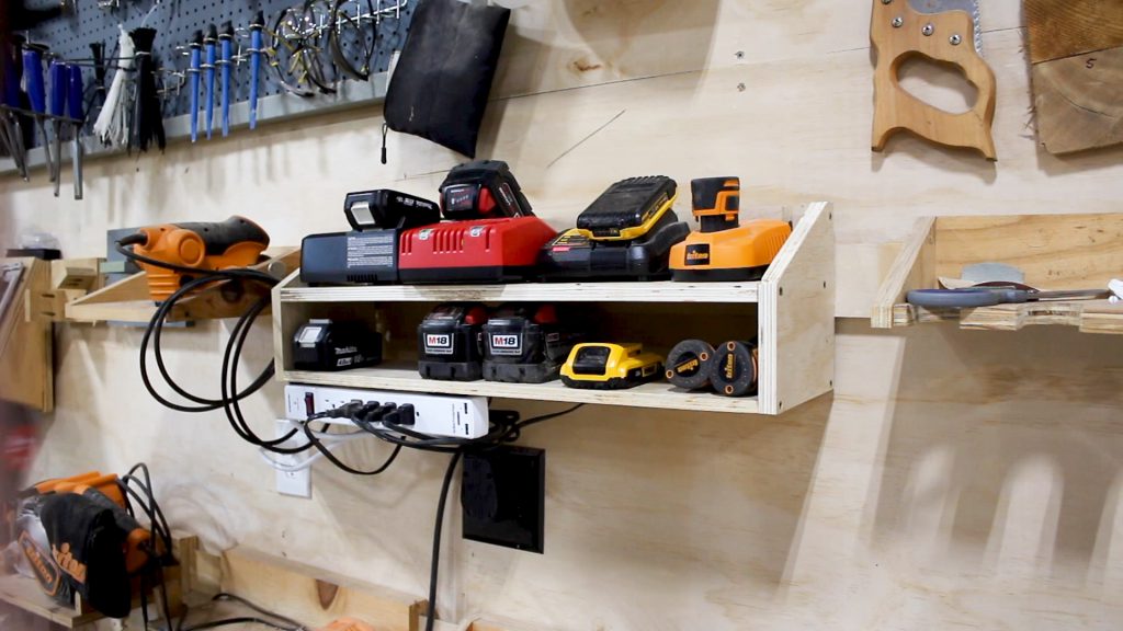
Next I started working on a battery charing station. I have one charger from each manufacture so I wanted a simple shelf that could keep them all together and organized for me. I again reached for some scrap, this time going with 3/4” plywood. I measured the chargers I have to store then cut a bottom and a back to create a shelf.

Before joining things together I laid the chargers out on the shelf and marked off where the power cords of each, fell on the shelf. Then I cut this location out over at the bandsaw. This will give me a place to route the cords later on.

I stuck things together with Titebond Original wood glue, using my Super Jaws to help hold things down, while I pre drilled and used screws to attach the two pieces.

Next I cut some wings that will not only give the shelf some support but also act as the sides of the lower shelf that will hold the extra batteries. To make getting the shape of this side wing easy, just set your shelf on end and trace the profile. I made my lower shelf 4” but measure your tallest battery and see if you need yours to be taller. After getting it cut at the bandsaw, I once again used glue and screws to attach things.

Now I just measured in between the two side wings and cut a shelf to fit between. I added in a few French cleats on the back then set it in place and loaded it down with power tool batteries and their chargers.

I did add a power strip, and this is so I can plug all my chargers into the strip then plug the strip into the wall.

Alright then the last thing I decided to do was installed some ceiling mounted, steel storage racks made by a company called SafeRacks.

I have installed this racks in my garage before so I already knew how quick they were to install and just how handy they are at getting those larger items that I need to store, off the floor and away from the valuable lower wall space, and up higher where they are still assessable when I need them.
I started off by placing the ceiling brackets into the joists.

After getting these attached I went back down to my workbench and started assembling the vertical arms. This is where you can adjust the height of the entire unit. To determine the height of mine off of the ceiling, I measured the totes I would be storing and decided that 3’ would be plenty.

After getting all four set to the same length, I hopped back up on my scaffolding, very quickly attached them, and then started putting in the cross members that make up the body of the shelf.

These SafeRacks do come in a variety of different sizes but I went with the 4’ x 8’ model, and airing on the side of cation once again of leaving myself extra room for extra inventory, I installed two of them. I’m not sure what the weight capacity is for the smaller racks but these 4×8’s are rated at 600 lbs. So that’s quite a bit of stuff these can hold!


I actually built another storage solution for the shop and that is this finishing rack which holds all my paint/stain/tube of caulking/and glue bottles. This was a few weeks ago when Triton Tools and Matt Cremona came to visit and Triton actually captured the project and produced a full video with a lot of fun behind the scenes included. Click here to check that out.


Be sure and watch my full video at the top for a more detailed tutorial of these projects. I hope yall enjoyed this one and I hope ya’ll go out there and clean those shops! See you on the next build.
The post 4 Shop Organizing Projects appeared first on Wilker Do's.
from Wilker Do's https://ift.tt/2Fl7iwp
via Ronald Bosley III on Blogger https://ift.tt/2MdONsZ
Posted on November 12th, 2018
Ronald Bosley III on Blogger: Protected: Modern Live Edge Waterfall Coffee Table
Ronald Bosley III on Blogger: Protected: Modern Live Edge Waterfall Coffee Table
https://ronaldbosleyiii.blogspot.com/2018/11/protected-modern-live-edge-waterfall.html
Protected: Modern Live Edge Waterfall Coffee Table
The post Protected: Modern Live Edge Waterfall Coffee Table appeared first on Wilker Do's.
from Wilker Do's https://ift.tt/2PFcoaA
via Ronald Bosley III on Blogger https://ift.tt/2MdONsZ
Posted on November 5th, 2018
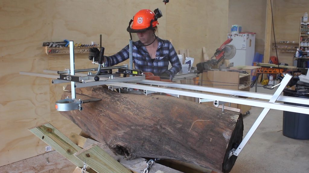
Ronald Bosley III on Blogger: Chainsaw Mill: How to Slab Logs
Ronald Bosley III on Blogger: Chainsaw Mill: How to Slab Logs
https://ronaldbosleyiii.blogspot.com/2018/10/chainsaw-mill-how-to-slab-logs.html
Chainsaw Mill: How to Slab Logs
Things I Used:
Last week I modified a trailer to go get some logs, this week I’ll be slabbing them up. As milling is an entire world of it’s own in the woodworking niche, I learned a crazy amount in just a few days and I’m going to try and cram as much of that information into this video as possible, so lets gets right to it.
There are two main methods for milling logs: a bandsaw mill like Matt Cremona’s…

…or a chainsaw mill. I’m going with a chainsaw mill…..for now. Tractor Supply is now a supplier of Husqvarna equipment and I’ve partnered with them to use the Rancher 460 chainsaw with a 24” bar on my mill. Note that the chainsaw you buy has specs on the longest bar it can support. So if you want to cut certain diameter logs, be sure to buy a saw that can support it.

I’m actually going to jump ahead because there are a lot of components to this one so let me show you the final outcome before I get into the details of each one.
The components are: the chainsaw of course. Next is the mill which is a railing system parallel to the chainsaw bar that guides you for a straight cut.

On your very first cut, you need a flat reference for the mill to ride along, which is what these rails here are.

Then something I put on mine but is optional is a winch. This is mounted to the mill then hooks up to this bar you see here.

Now that you see what I end up with, let get back to the beginning of putting it together. I started off with the rails that will go ontop of my logs to give my mill a flat reference for the first cut. You might have seen people use a ladder for this application before, but I went with rails made by the same company who made the mill I’ll be using which is a family owned business called Granberg. They are called EZ Rails and do come in a variety of different lengths but I went the 10’ rails which come in two 5’ sections that can be used separately or together. They have these cross bars with spikes and this is how the rails are attached to the log.


Next I switched out the stock chain on my chainsaw, which is a crosscut chain, to a ripping chain. Just like any other saw blades, the teeth are designed with a certain task in mind and if you are going to go from crosscutting to slabbing, you need to invest in a ripping chain. The teeth are filed to a steeper angle on ripping chains since it’s a much more aggressive cut since you are cutting along so many more growth rings lengthwise.

After getting the chain on and tighten down, I moved on to assembling the mill that goes around the chainsaw. This is the railing system that is parallel to the blade, and it can be raised or lower to determine the thickness of your slab. Since I have a 24” bar I went with the 24” mill from Granberg.

And just a fun fact, Elof Granberg, who started the company, designed the first Alaskan chainsaw mill back in the 60s. So anything milling related, the company has.
You can see that the chainsaw now fits right into the mill then tightens down on the bar to hold onto it.

Like I mentioned earlier, an add on I opted in for is a winch on the mill. This will drastically reduce the amount of work I manually have to do to get the saw through the piece of wood and I’ll show you how this works in a few mins.
First I want to set all that equipment aside and quickly build a log stand so I don’t have to cut these logs on the ground. Since I’ve never done this before I wasn’t sure what set up would be best, so I went with some 2x6s with a steep angle cut in at both ends on my miter saw, then a hole drilled in the center. I flipped them around to be opposite of one another then stuck in a bolt with a few washers and nuts. I used two nuts so that I could keep this joint pivoting which will make the stand foldable.


After repeating to make three the same, I lined them out, used a clamp to hold them in an open position with the feet flat on the floor, then placed another 2×6 to tie them together, and to also create a hard stop. A 2×6 was placed on both sides and now you can see it can fold up and be stored or transported, but then quickly deployed to be used. Depending on your length of logs, should determine how many of these Xs you include on your stand.


Ok! After all that assembly I was finally ready to get a log set on my stand and to start milling. Cody used the tractor to snatch onto a log on the trailer then set it in position. Now the log doesn’t have to be perfectly flat but the next step is easiest if it is somewhat flat, so I first started up my 460 and took off a high spot.


With this being the first cut, I started by placing my EZ Rails in place. Again, these will be the flat reference for my mill to get a straight first cut. I lined up the cross members so that the spikes, or dogs, would all land on the log then I hammered them in.

With it attached I next leveled up the rails. You don’t need them to be level along the length of the log, just across the log, I don’t know if you can see but there are two leveling screws at each one of these cross members to make this happen.

Then the last thing to attach is the winch’s anchor point. If used, this is attached to the end of the log so that it can peak up in between the two rails. And you can see here that once you start the saw and get the mill set on the rails, the winch cable goes from the reel to this anchor point then attaches back to the mill. This allows me to keep my left hand on the throttle of the saw, and my right hand on the winch to advance or back off on the cut.
A few things I want to say:
1) Beware folks because this is highly addictive. I want to slab up everything now to where if you stand still long enough in my shop, I’ll start attaching the rails to you!
2) This operation can be done alone but it’s kinda a lot and is sooo much easier if you have a second hand around. You’ll see Brain there cutting wedges for me and placing them as I get further into the log. This is to keep the slab from pitching your bar and binding.
3) I tried moving the mill along without the winch just to see the difference and I’ll say that the winch makes such a huge difference in how much effort is required. I 100% recommend it if you get into this.
After getting through my first cut (which took 6.5 mins btw), I set the top aside then started on the second cut. Now that the log has a flat reference along the top I no longer need the EZ Rails, I can just set the mill directly onto of my previous cut and start the process over again. The only thing I had to do before making this cut was to adjust the depth of my mill to the slab thickness I wanted. I set it for 2” then got after it.

I am really shocked at how quickly I was able to get through an entire cut, this second cut took me just under 5 mins to make. The main components for making that happen is much like any other cutting tool in the shop…..the right power source and a sharp edge. This Husquvarna had no issues chopping through this oak, mesquite, or even pecan which are all pretty hard woods. This work does use up the bar oil though, so make sure you are keeping an eye on your tank.
Now I won’t lie, I was pretty disappointed at this oak when I got a look inside. I was hoping this thing would be beautiful but the log was apparently pretty old and very dried out so the inside was really cracked and honestly not something I was interested in keeping. Looking back on it though, I think testing and tuning, getting things figured out on a junk log is a pretty good way to go. Like anything else you learn so much on your first go and I still had a blast.
I didn’t have any more long logs but my neighbor offered me a short pecan and mesquite log so I jumped at those to try next. You can see that instead of cutting the tops of my log stand down, I just shored up the bottom with some scraps. This is because I’m not yet sure what the average diameter of log I’ll be getting is, and I didn’t want to cut them too short but note that it is an alternative to filling up the bottom.

Something else I did when the log got smaller was use the log jaws in my Super Jaws. These are a set of jaws with blunted teeth specifically designed for grabbing onto logs. Oh and a helpful tip I got from Instagram is instead of placing the log level lengthwise, place it downhill so that gravity can help you when you are milling through.

As far as keeping things sharp, I sharpened my chain after every third pass which might be excessive but I’ll learn with time where the sweet spot is on sharpening. In the past I’ve always used a file to sharpen the teeth but Grandberg has this 12v electric sharpener that attaches right to the bar. It hooks up to a truck or car battery so I used the battery from the log snatching trailer to run it. Even if you don’t get into milling this sharpener is worth getting.

The last thing I had to slab up with this crotch piece of pecan, after making the first cut I stuck it in my super jaws to make the remaining cuts and just look at how cool this one came out!

The next step is to set the slabs aside to dry and a general rule is it takes one year for every inch of thickness. So a 2” slab should be left to dry for two years. For video sake, lets say it’s been two years and these are now dry and ready to be used to make something.
I’ll first need to flatten the slab. Since it’s much wider than a jointer the most popular method for flattening slabs is called a router sled. You can make a home made jig but my friends over at Woodpeckers Tools heard I was slabbing and asked me to try out their new slab flattener coming out later this year. If you are familiar with Woodpeckers then you’ll know they excel at precision which is exactly what a flattener needs to get the best results. Everything needs to be level and stay level to give you a perfect cut across your entire slab so you don’t have a lot, or any post clean up work to do. The jig has two long rails that I temporarily attached to my workbench, then it also has a sled that sits onto these rails. Inside this sled is where a router base is set so that it can slide up and down the length.


After taking my time to get everything set up, I positioned my slab and set the depth of my router bit to start removing material to flatten the slab. I’m using my Triton 2 1/4” Router since I have my larger 3 1/4” in my table. Then for a bit I’m using a 2” flattening bit and also a bit extender made by Infinity. If you don’t have this extender and you just have the bit in your router, it’s really common for the bit to run out of throw and not get down far enough to hit your slab.

With things set up you can see how it works. The router base moves along the sled then the sled moves along the rails. Allowing you to gradually move over the slab in order to flatten it. That is a wicked cool tool if you ask me.

If you have never flattened a slab before then here are a few things I learned from my experience.
When working with a piece that has a slight twist in it, you first need to shim it up and keep it stable to flatten it. I would find the two corners that were rocking then stick in a few wedges.

Next I set the bit according to the highest spot on the slab so that it starts off with removing the high spots. This means you aren’t removing material everywhere on the slab on the first pass. The objective is keep removing all of the high spots pass by pass until you are finally removing material from the entire slab, meaning it’s all on the same level and is flat.
I set the bit to take off about 1/8” material. Also remember that with a larger diameter bit, you will want to slow the speed of your router down. I have my router set to 2 out of 5. I start on one side of the slab, move the router across then bring it back. Once I bring it back I move the entire sled down the slab to advance the cut. And that’s it, it’s just a matter of repeating until I make it across the entire slab.
Once I get the slab down to where I’m removing material from everywhere evenly, I change the bit depth for a final smoothing pass. And this is to just to cut down on some of the marks left behind from the rough cuts, but honestly if you keep your bit sharp you’ll be amazed at how perfect the surface feels.

I hope you found this informative. I cant believe the mount of information I learned in just a week! And of course, now I cant wait until I have my own inventory of wood that I’ve milled up myself. Stay tuned for my next video which will be turning live edge slabs into furniture.

The post Chainsaw Mill: How to Slab Logs appeared first on Wilker Do's.
from Wilker Do's https://ift.tt/2qll9Z9
via Ronald Bosley III on Blogger https://ift.tt/2MdONsZ
Posted on October 31st, 2018
Ronald Bosley III on Blogger: Easy Log Slabbin Stand – 2×6’s and Bolts – Check it out!
Ronald Bosley III on Blogger: Easy Log Slabbin Stand – 2×6’s and Bolts – Check it out!
https://ronaldbosleyiii.blogspot.com/2018/10/easy-log-slabbin-stand-26s-and-bolts.html
Easy Log Slabbin Stand – 2×6’s and Bolts – Check it out!
Y’all may have seen recently that I’ve started playing around with log slabbin’. It wasn’t until I built the log lifting trailer, harpooned a couple of logs, then got them back to the shop, before I realized I would need some sort of stand to set the logs on while I slab them up. After combing through the inter-web for some basic design inspiration, I settled on a collapsible model made from some basic 2×6 material and a hand full of tools that would slip perfectly into a stocking stuffer for your special DIY girl or guy. Here’s how it all came together:

I began by cutting some 2×6 to about 30” long with a 45 on each end. These pieces get joined together with a shoulder bolt which allows the pieces to pivot. Im using a 1/2” bolt with two nuts installed per bolt. The nuts get torqued into one another to ensure the bolt does not lose over time and it ensures the two pieces of material don’t get squeezed too tight and fail to slide past one another easily.
To drill the bolt holes I’m using a light Makita hand drill and these Daredevil Spade Bits by Bosch. Not only are they inexpensive at 20 bucks for a lot of 12 bits, but they also have some cool features that help produce a nice through hole.

The centering tip of the bits is fully threaded up it’s tapered profile which helps keep the paddle bit pulling through the wood. I surprised at how the bit feels as though its just driving itself through the material and how little I was having to push the bit through the hole.

Once all the holes were drilled, and the X’s were joined using nut and bolt hardware, I used a couple more 2×6’s as cross members to join them together.

Understanding how tall the top ends of the X needed to be was a bit of a gamble. I knew I needed something somewhat tall for a large log but if I cut it too tall then the top of the X would get in the way of my log slabbing mill. Basically, I was just shooting from the hip during the entire construction of this thing so it was no surprise I needed to do a little post process cutting.

To whack the tops of these 2×6’s off I used yet another inexpensive piece of gear that zipped right through the material like a hot knife through butter. Enter the Diabo 9”Wood Cutting Recip. Saw Blade. Diablo has been killing it in the recIip-saw blade industry lately and makes quality cutting super affordable.

Aside from the 2×6 getting cut to a more manageable length, I also cut down the extra thread on the bolt tails using another Diablo blade used for cutting medium metals with it’s carbide teeth. If you think that cutting metal with a sawzall sounds like a ride on a mechanical bull for your forearms you’d be for fitting the opportunity to feel just how smooth these metal cutting blades perform. With their permashield coating and 10 tooth per inch design, these metal cutting blades really smooth out the entire cutting process and don’t leave your forearms feeling like jelly after a days worth cutting

The stand worked perfectly for my first log! I was so darn happy to have a slab of wood cut from my very own labor : ) Typically, one would allow a slab to dry according to its thickness before beginning to work with it. BUT! I recently got my hands on a new flattening jig from Woodpecker Tools and couldn’t wait to test drive it.

Flattening jigs can be made from basic materials and a router and work a lot like a conventional upright mill in a machine shop. Wit a large surfacing bit, you find the high spot of the material and slowly mill away material from the highest spot to the lowest spot to create a level, flat plane.

The only down side to this entire operation is the DUST! Holy moly does this process make a mess. I had sawdust every where! The mess on the work bench was knocked out pretty quick using another little tool that all shops oughtta have; a basic shop-vac. The Home Depot sent me this 4.5 Gallon, 5 horsepower Shop Wet/Dry Vac from Ridgid. It comes with 20′ of cord, a three layer filter, and has enough sucking power to pull a golf ball thorough a garden hose lol….ok maybe not that much but this thing is plenty stout for shop use. Ridgid changed up the design on this model and made it look a bit more like a tool box which stores all of the bits inside small enclosures instead of crowding up the exterior like the conventional modes. With a little bit of work this thing knocked out my ultra messy workbench in no time!

Thanks for stopping in to learn a bit more about this kind of project as well as the handy tools. All of this gear is available through The Home Depot. This article is actually sponsored by them through their ProSpective campaign which involves paid content creators, like me and several others, who provide feedback, exposure, and reviews of current projects available to the market. Some of the links above are affiliate links and provide a small kickback for any sales associated with them. In a way, it helps to keep the entire machine running. Thanks so much for your support and stay safe out there!
Cheers – April
The post Easy Log Slabbin Stand – 2×6’s and Bolts – Check it out! appeared first on Wilker Do's.
from Wilker Do's https://ift.tt/2OQbhFr
via Ronald Bosley III on Blogger https://ift.tt/2MdONsZ
Posted on October 27th, 2018
Ronald Bosley III on Blogger: Simple Shelf Made Easy With Some New Gear – Check it out!
Ronald Bosley III on Blogger: Simple Shelf Made Easy With Some New Gear – Check it out!
https://ronaldbosleyiii.blogspot.com/2018/10/simple-shelf-made-easy-with-some-new.html
Simple Shelf Made Easy With Some New Gear – Check it out!
My well house has been a “catch all” for a variety of old things Cody and I are holding onto for the “right project”. Steel boxes, tires and wheels….different odd ball things that are kinda bulky and taking up valuable space. Today I tackled a simple shelf made from untreated two- by material with a hand full of pretty awesome late model tools you put on somebodies “nice” list. This shelf design is made up of (3) 2×6’s and (2) 2×4’s and is adaptable to almost any wall, especially those with exposed studs. After it was fully loaded, I reckon there was probably about 200lbs up there and it didn’t budge. Here’s how it all went:
First things first, clear all this mess out of the working pace:

After heaving all the heavy cargo out of the well house, I got an inside dimension from wall to wall. Inside dimensions over an open space can be a little tricky if you’re dealing with a bowed tape. Since my well house does not have a floor, rolling the tape out on the deck wasn’t really an option.
Enter the laser measuring device. These things have been around for ages and this one may be one of the coolest ones yet. Bosch calls this unit the GLM 50C BLAZE 165 and it is one handy tool. It has a full color display that’s easy to see in low light conditions, it’s accurate within 1/16”, offers metric or standards dimensioning (decimal or fraction), and a whole host of handy features built within its sub-menus. With just a few strokes of the wrist along a couple of dimensions, this laser measurer can calculate area, volume, and even dub as a level.


I measured twice then committed to start cutting all the shelving material. For all the cross cutting I’m throwin another new tool into the rotation with this cordless unit from DeWalt. Back when I was building the shop I used a mini-DeWalt cordless circ-saw like it was going out of style. For a little guy, it worked really well but with a 6-12” blade it had some limits. This new saw is the big brother to my mini and packs some serious punch. It’ll plunge down to a full 2-9/16” depth and runs off a single 6.0 Ah battery.

The brushless motor is silky smooth during cuts and is unbelievably quiet. To be honest, this was one of the main draw backs for the mini saw; it’s pretty darn loud. : / In terms of pushing the saw through the material, this saw feels as solid and refined as any other quality shoed SkillSaw or Makita (two of my favorite corded circ-saws).
With the top 2×6’s and lower 2×4’s cut to length, I began attaching the first sticks of material in place. I began with the 2×4 horizontal members that will support the shelf deck. These got faced nailed to the studs of the wall just above shoulder height. Here again, The nailing went in like warm butter with the help of yet another awesome tool from DeWalt. This one is a 20V cordless nailer that shoots 21 degree collated nails.

The nailer worked perfectly, but it took a little getting used to the time it takes to build up it’s baby compressor once the head is depressed. If you treat it like a conventional pneumatic nailer and shoot it as soon as the head is compressed, you will find you’ve outrun the clock and have to wait just another short moment for the optimal pressure for firing. For a project like this easy shelf, this is not really a problem but I could see that being a potential issue on a job site.
Before throwing the decking up on all the horizontals, I cut some 20” – 45 degree corner gussets to support the weight of the shelf. One end got face nailed to the stud and the other end gets a long 3” screw where the gusset meets the horizontal.
At this point I was ready to install the decking but was torn on two different approaches. Notch my 2×6 deck material to slide over the studs or no? I took a second to look at how that would work and made a quick cut with a Dremel multi tool. If you haven’t taken one of these for a ride you really ought to!

The high speed oscillator is one of the coolest tools to hit the market in a long time since it can get into some insanely sight spaces and comes with a huge variety of clever cutting heads. It also works well for making this inside pocket cut and creates nice clean inside corners. This multi tool is one of the latest to hit the market and features a tool-less blade change mechanism that really simplifies swapping accessory heads. Occasionally you can find bundle deals on these accessory heads like this package as well as this package.

In the end I decided to scrap notching out material for the studs since all of the items intended for the shelf are large and unlikely to need material all he way inside the stud bay. Nonetheless, the Dremel MULTI-MAX is a must have tool for a variety of sanding, cutting, and finishing jobs.
The final step in this construction was required putting up the 2×6 deck boards. Now you might be thinkin this is a bit of overkill….and you’d be exactly right. But for the heavy chunky items I’m throwing up here, this shelf is going to work perfect. All the deck boards got sucked down with 3″ deck screws….which bring me to the the final piece of gear you could consider for that special crafty person in your life, even if that person is you : ) lol
Hardware storage is multi-faceted necessity of the creator’s life style. You not only need hardware storage solution for the shop, but you also need a quick grab and go solution for the times you’re going to be working well away from your shop….trust me, no one has time for silly little trips to the shop or the hardware store for simple things like bolts, screws or washers. Tah-dah! Enter the Small Parts Organizer from DeWalt. trust me when I say these things are way to cheap and way too handy to not give em a try! I’m talkin 20 bucks for the big one and 10 bucks for the small one. Easy Day!


These parts organizers are loaded with quality features throughout; over center toggle latches for a nice positive closure, clear acrylic lid that’s water tight and snug to the cargo compartments to prevent spillage of even the smallest washers, and you can stack and lock multiple boxes together for the ultimate grab-n-go hardware solution. My favorite part of the large box are the removable bins. Previous models have featured simple divider walls but the removable bin is the only way to go.
Pulling from the large well of deck screws, I cracked on with securing the deck boards in place. I set the outer board first, then butted the inner board to the studs, and finally just eye balled the middle board on center between the two.

Finally, I heaved all that mess up onto the shelf and called this project a wrap. I cant stand clutter!!…..and with a little help from some quality tools, I was able to nip this mess at the bud and not have to trip over these odds-and-ends when I need to get in to my well house.
Thanks for stopping in to learn a bit more about this kind of project as well as the handy tools. All of this gear is available through The Home Depot. This article is actually sponsored by them through their ProSpective campaign which involves paid content creators, like me and several others, who provide feedback, exposure, and reviews of current projects available to the market. Some of the links above are affiliate links and provide a small kickback for any sales associated with them. In a way, it helps to keep the entire machine running. Thanks so much for your support and stay safe out there!
Cheers – April
The post Simple Shelf Made Easy With Some New Gear – Check it out! appeared first on Wilker Do's.
from Wilker Do's https://ift.tt/2PqI3fR
via Ronald Bosley III on Blogger https://ift.tt/2MdONsZ
Posted on October 27th, 2018
Ronald Bosley III on Blogger: Building a Log Hauling Trailer
Ronald Bosley III on Blogger: Building a Log Hauling Trailer
https://ronaldbosleyiii.blogspot.com/2018/10/building-log-hauling-trailer.html
Building a Log Hauling Trailer
Things I Used
Maybe it’s because I now live in the country, or maybe it’s because I’ve been hanging around my buddy Matt Cremona too much….but I want to play around with milling some logs. I intend to build a chainsaw mill next week then tackle the giant Matt Cremona bandsaw mill in early 2019. Before that though, I need to modify a trailer so I have a way to go pick up logs and haul them home. That’s what I’m doing this week.


The premise is to make and attach an arch to the back of a trailer that can pivot forward and backwards. You connect a winch to the arch, then you can tilt it forward to grab onto something, then winch the arch back to pull it up and onto the trailer.
Now that you see what I’m going after, lets get into building it.
This project might seem big, and I suppose it is in size, but it’s actually a pretty simple build. Also, I’m using it in this case to haul around logs but it’s also worth mentioning that this design would be good for lifting and hauling anything that’s big and heavy that you can get a chain around. I personally have a lot of rocks on my place I’ll be going after next.
I started off by cutting the tubing I’ll use for the arch to length. I’m going with 1/4” material for almost this entire build. We don’t have the stellar tree diameters that you in the north do, but I still want to build this thing heafty so I’ll always have the power should the need arise.


For the mean time I only cut the four bottom parts of the arch. I didn’t want to weld the complete arch on my shop floor then the risk it not fitting exactly right on the trailer. So next I started prepping these parts to be welded. I started by sticking each one in my Triton SuperJaws and grinding in a bevel on all the edges that would be welded to another joint.

Then I moved the parts back down to my floor and stuck them together. I first tacked them into place then welded them close. For this project I’m using my Power Mig 210 MP Machine and if you’ve been wanting a welder it’s worth noting that this machine is currently on sale. You can save over $400 until November 8th, 2018 by using the promo code PM999 at check out over at LincolnElectric.com


Now Cremona has his arch mounted permanently to his trailer, but not yet knowing how often I’ll use mine, I wanted the arch to be removable. I’ve been traveling a lot recently so Cody actually tackled designing this removable system for me. Then on top of that he even cut out the parts needed with my Torchmate CNC so everything was ready for me to assemble. Annnnd he even got footage of it! What?! What a guy. I do have these tool paths available for download in the plans section of my website if you’re interested.


These mounting brackets have a bottom plate that will be attached to the deck of the trailer, then two vertical plates that will sandwich either side of the arch. Then all three components will get a hole so a pin can be placed all the way through. This will create the pivot needed but also make the arch removable should we want to use the trailer for regular hauling.
I started these off by lining out the placement of these side plates, the important thing here is to make sure they are parallel to one another. You wouldn’t want that arch pivoting up and having an interference issue.
I’m using a 1” diameter pin and to give it a little more support than the 1/4” plate material, I welded on some collars, just cut from a 1” steel pipe, onto the outside of both side plates.


Next I set it onto the trailer and threw a level on it. Not surprisingly, the deck of the trailer needed some attention before the plate would be level. Note: you do want to make sure your trailer is level before reading level on this bracket. To fix my unleveled situation I used my 4” belt sander to take down the high spot on the deck. After fine tuning the left and right I moved on.


With that done I moved to working on reinforcing the bottom side of the trailer with some steel. For this I’m going with 1/4” angle iron and the important thing is for this angle iron to line up with the holes in the mounting brackets. Instead of welding the brackets to the trailer, they will be attached using nuts and bolts so they too will be removable. The arch will be removable with the pin but should we need/want to remove these brackets as well, then we easily can.
So back to placing this angle iron, I first transferred over the hole location from the mounting brackets to the side of the trailer. Then I cut the angle iron to length and stuck it in place…be sure to leave room for not only the bolt but also the washer. I used some scrap wood to build up the deck some so I could get a clamp in place to hold it while I set up to weld.

I placed a piece like this in line with the front holes as well as the back. Then started drilling the holes through the deck and through the angle iron. I am using 1/2” hardware but started off with a small bit then stepped up a few times until getting to a 1/2” bit. Oh and the important thing here is to make sure these plates are parallel to one another, just like the plates on the brackets. You want everything on the same line so that the arch doesn’t run into anything going up or coming down.

Once all eight holes were drilled, I stuck the hardware in then tightened everything down.

Now while I was working on all that, Brain was working over at my puny drill press, punching a hole through both of the uprights. It was a 1” hole through 1/4” material so it was a job that required patience. By the time I was done with the deck, he was done with the holes so I took the uprights and smoothed out my welds with my grinder before pinning it onto the trailer.


To attach them to the trailer, I set it in place between the two vertical sides plates on the mounting bracket. Then moved to the end of the leg so I could lift up on it, align all three holes, then shove the pin through. It’s worth noting these pins come with a hole in the end to place another pin to keep this pin from coming out. Which of course is a good safety. And now you can kinda see how it will work….

After getting the other side mounted I squared up both uprights to each other and the mounting brackets, then took a dimension for the final arch piece. I cut it to length then welded it in place. It’s not only easier moving the arch into place, building it this way but it’s also a safer bet over fabbing it on a shop floor, moving it into place on the trailer, and hoping everything lines up.


With that welded up, the last bit on the arch was to weld on some gussets over each one of the seams. These I hand cut with my Tomahawk plasma cutter because I used thinner material. For these I went with 3/16” material. I only placed these on the front of the arch so I have four total. The middle two were easily done with the arch laid down but the fender wheel of the trailer got in the way of the outer two so I stood it up to complete these.


Now while I worked on the arch Cody and Brian were figuring out how to mount a winch to the trailer so it could work! I actually went out of town the day they were working on his portion and unlike earlier, they did not get me any footage, but here an overview for ya.
Cody cut out a giant plate on the CNC plasma cutter to fit in the tongue of the trailer for the winch to sit on. He welded it to the bottom side of the trailer instead of the top side so that when the winch is under load it will be getting pulled into the tongue vs being welded from the top it would just pull against the welds.

The winch and battery were mounted then a heavy duty D Ring was welded onto the arch to create a grab point for the arch.

And that’s pretty much it! Next we just had to go find a log to test it out. A buddy offered two down oaks at his place for us to remove so we loaded up and took off. They both had giant root systems still attached so I first cut those off to make hauling them up on the trailer easier.


I’m already considering some add ons to make hauling easier. Somebody on Instagram suggested adding Jacks to the back end of the trailer, which I think is a great idea. Then I’m also playing around with the idea of ramps with rollers in it to make getting the log up and over the trailer lip easier. But we’ll see! Of course if I do any modifications I will be sure to bring you guys along.
If you have doubts about what something like this can handle then be sure to check out Matt’s Instagram and YouTube channel as he lives where the beast trees are but his arch trailer hasn’t met one it couldn’t handle yet. Also he has been into urban logging for years and has a ton of knowledge on the subject.
That’s it for this one. Watch my video above for a better look at this project. And stay tuned for the next video where I build a chainsaw mill and slab up these logs. I’ll see you soon.
The post Building a Log Hauling Trailer appeared first on Wilker Do's.
from Wilker Do's https://ift.tt/2q73AMe
via Ronald Bosley III on Blogger https://ift.tt/2MdONsZ
Posted on October 24th, 2018
Ronald Bosley III on Blogger: Schedule Commercial Asphalt Maintenance This Fall Season
Ronald Bosley III on Blogger: Schedule Commercial Asphalt Maintenance This Fall Season
https://ronaldbosleyiii.blogspot.com/2018/10/schedule-commercial-asphalt-maintenance.html
Schedule Commercial Asphalt Maintenance This Fall Season
If you own a commercial shopping center that needs professional asphalt repairs in Burlington County, the team from Asphalt Pavement Solutions is who to turn to. We are one of the most trusted asphalt companies in the area and always go above and beyond with the services we offer. Learn more about our parking lot…
The post Schedule Commercial Asphalt Maintenance This Fall Season appeared first on Asphalt Pavement Solutions.
from Asphalt Pavement Solutions https://ift.tt/2pWGlo5
via Ronald Bosley III on Blogger https://ift.tt/2MdONsZ
Posted on October 18th, 2018
Ronald Bosley III on Blogger: Ultimate Mobile Clamp Rack
Ronald Bosley III on Blogger: Ultimate Mobile Clamp Rack
https://ronaldbosleyiii.blogspot.com/2018/10/ultimate-mobile-clamp-rack.html
Ultimate Mobile Clamp Rack
Things I Used For This Project:
This week I’m tackling a problem that I’m thankful to have, and that’s having so many clamps! Noticed I didn’t say too many, as there is no such thing. Recently a local cabinet marker retired and sold me his entire stock of Bessey clamps. And instead of adding to my wall mounted system I’ll be building this mobile rack so I can wheel all of my clamps over to a work surface instead of carrying them a few at a time. Lets jump into how I did it.
When doing a basic search for mobile clamp racks I ran across this Infinity Tools video and loved the simple but effective design using plywood so I started off by replicating the body.

I started by setting the boards on my workbench and drawing those two unique side shapes on a sheet of plywood then using my track saw to cut them out. These look like an Erlenmeyer Flask where it’s wider on the bottom and narrower on the top and I can tell you now that I’ve built it, that the rack doesn’t feel at all top heavy, even when fully weighted down.


The rack does take two sheets of plywood to complete the build and you’ll notice that I’m using a new assistant in my shop. It’s a new panel carrier to hit the market called Hercules Dolly. Instead of woman-handling full sheets over to my workbench, I’m now able to set the front end of my sheet on the Hercules Dolly then very easily maneuver the sheet over with no effort at all. You can place the dolly at the front if you need to drive it around items, or more near the center of the sheet to take more of the load or to give you a good balance point should you want to also use the dolly to help lift the sheet of plywood.


If you’re interested my friends at Hercules Dolly have given me a 10% off coupon code for y’all. For the next two weeks, if you use April at checkout then you’ll get 10% off your Hercules Dolly.
After getting both sides and the bottom cut I started joining things together, using the help of these right angle clamps.

Next I moved the entire thing to the ground to make attaching that center board of plywood easier. I laid it on it’s side and marked off where the board needed to be place then laid down Titebond Original wood glue. I stood the unit up to attach it with screws and even though I had that pencil mark on where the board needed to land I found it easier to cut a spacer, clamp it in place, and just butt the board up to it then screw it down. After getting done with one side, I repeated on the other side.


Next was more glue then attaching the front lip to create a bottom shelf. These I screwed in from the sides but then I also flipped the unit over to attach it from the bottom. Here I took the chance to also secure the center board in a few places from the bottom as well.


I wanted to make the unit mobile so next I added some heavy duty casters and I do recommend investing in some good casters for projects like this. I first beefed up the area they would be mounted to the rack because it will be hauling around a good bit of weight when it’s fully loaded down. I chose to mount these pads on the inside of my unit to avoid adding height to the rack but if 3/4” doesn’t make a difference to you, these can also be mounted to the bottom so they aren’t seen.

My friend and fellow content creator Maker Gray was hanging out with me so I recruited her to help me test out the rack. I better get out of there before we decide to start throwing knives or something. haha.

Alright now to move on to customizing this unit to really be functional. This is where things might vary for you since everybody’s clamp collection is different. I recommend pulling out every clamp you own, pull a few dimensions, then dictate the number and placement of the holders that will make the most of the space for you.
All of my holders are extremely simple, put together with wood glue and brad nails then attached to the rack using pocket holes. I didn’t use any glue when attaching the holders because as my clamp collection changes I want to have the ability to move things around and reorganize.


Since I have so many Bessey K Body style clamps, I’m dedicating an entire side of the rack to them. I sped up the process by batching out the holders by tapping the plywood cuts together then running them through the bandsaw all at the same time. This creates the triangle support piece on the bottom side of the shelf. After drilling a few pocket holes in each shelf I attached things with glue and brad nails.


To save on space, I’ll be storing all my really long clamps vertically but all the medium sized clamps horizontally and it’s extraordinary how many clamps I was able to jam in doing it this way. 42 if you’re wondering!
Just a tip when you’re placing these shelves, set one screw but be sure to throw a level on it before setting the second. This will make things look really tight and sharp in the end. Once I placed enough shelves to mount all my clamps of this style I attached a small lip to the front of each holder to keep the clamps from being able to slide off while moving the entire rack around. Oh another tip for you: I discovered that a shelf would hold four clamps if I placed them all facing the same direction, but if I alternated the heads then I could fit in six clamps on each shelf. So if I need more room in the future I could consolidate and free up more space along the bottom.

Alright, now onto the other side. I had a few more extra long K Body style clamps so I first included a similar shelf on this side to house those. But then I started making shelves suited to hold the Rockler Surefoot bar clamps, which since I’ve never owned K Bodys before, have been my main go to clamps for glue ups.
These clamps are aluminum and very light weight so I kept their hanging brackets much simpler and left it as two shallow triangles with a few pocket holes in them to attach to the back. Now I had something unique planned for this side of the rack so I made sure all these hangers along the top would keep the clamps on this side inside the side walls of the rack itself. I’ll get to my reasoning later on, but note that if you don’t want to do any add ons like me, then you can make these brackets protrude past the side walls and hold more clamps to fit your collection in.


With the left over room on this side, I started making brackets and placing my other clamps including these Bessey KliKlamps and Duo Clamps.

Moving on to storing my F Style clamps. For this, I took inspiration from my buddy Tyson who did a really cool three layer wall mounted rack for his collection.

I started off by switching my blade to a dado stack that matched the thickness of the clamp’s neck. BTW another new thing in my shop I’m loving are these insert plates from Infinity Tools. Instead of cutting a slot in a new plate, they make a permanent plate with a slot for a removable insert. Once I cut into a new one, I write directly on the insert what cutting size it’s for so I can easily grab for it in the future.

I had to share that because I think it’s way too cool. Anyways, for cutting the slots equally you can of course measure across your board and mark off where to cut then manually move your board along, but I ended up using a really neat new jig put out by Rockler that makes this task a cinch.
The jig works so that you can set a metal gauge on the sacrificial fence to match the width of your dado cut. This way after you cut one slot, you can place that cut on this gauge then it will space all your other cuts equally for you. You’ll see that I went ahead and stacked two boards together while making these cuts because I wanted two boards for the top of the clamps as well as the bottom. Or at least that’s the case for the larger sizes.

To attach these holder I stuck with a few pocket holes along the bottom and secured them directly to that center board.


Now another thing to consider if you tackle this project is to place your clamps according to what you use most. My most reached for clamps are the bar clamps so I placed those in the prime position on my rack, then the F style clamps along the bottom. But if you use these more often, then place them higher an other clamps lower.
Oops – I skipped over the miter clamps. This was an easy shelf with some holes punched in it to match the diameter of the threads on these clamps. I added some triangle support wings then used pocket holes to attach it.

Then finally the last style of clamp I wanted to hang were these wooden hand screw clamps. These were the easiest as it was just a stumb out scrap piece with some pocket holes to attach it. You can see I made two different sizes for the three sizes of clamps I have.

I’ll have to play around and see what I end up using this bottom shelf mostly for but in the mean time I used it for accessories to gluing such as my gallon bottle storage, these tiny clamps that I placed in a bin, and these right angle clamp it jigs I so often reach for.

Keep in mind you could stop there on the rack but I had a few more ideas for add ons to take the unit another step further.
First thing was a glue refilling station. If you keep your small glue bottles close to full then you don’t have to squeeze as hard while applying. However, going from the gallon jug to the smaller one is always a challenge but Titebond has got our backs with a new pump to simplify the task. By adding in a shelf for my gallon jug to sit on, I’m thinking I’ll not put off filling up my smaller bottles as long as I normally do. Then on the same thought process, I went ahead and made another shelf for my small glue bottles to be housed in.


Ok this next add on is something I was very excited to try but understand that it’s an experiment so I might need to make some adjustments in the future.
What I’m aiming for is to have a glue up rack on my clamp rack. This will eliminate taking up workbench space for any small glue ups, which for me covers about 90% of my glue ups.
I wanted this attachment to be removable so I came up with a design that incorporates a French cleat. I started by making these cleats over at the bandsaw then attaching them to the rack on either end. This set up could end up supporting a good bit of weight so I went ahead and used wood glue on these.


Next I cut a board to length with a corresponding 45 degree angle cut on the bottom to fit into these cleats.

Then I made some dog ears, or some stand offs that I would cut and then attach to this board. These are so I could not only push out a metal rod from the board, but also provide the rod some support across it’s length.


With that looking like it would work I next started figuring out how to modify these Rockler Surefoot clamps so that I could hang them from this metal rod. These clamps already come with two holes punched near the end. I enlarged the last hole to match the size of my rod then took it to my bandsaw and cut away some material in order to create a hook. I cut in this hook on all my 24” and 36” long clamps.


Now you can see what I’m going for….. the glue up rack is removable so I can have it out of the way if needed but then quickly set into place when needed. Then I can hang my clamps with this hook and I can place the clamps anywhere along this rod. If I have a short boards for glue up then I can place two really close or four close, but then if I have a long board glue up then I can go up to 4’ wide with my clamp spacing.
There was still more to figure out though. Instead of having the clamps hang vertically I wanted to have them angled out some to make feeding in boards easier and to also push the glue up away from the rack for dripping glue to miss it. To achieve that, I first cut off the 45 angle in between the two cleats. This is so I could extend this board down further so I could attach another board to push out the clamps, but a little bit further than where it would currently land.
I took the rack off to make attaching this board easier but I didn’t use glue as again this is an experiment and I know I might need to make adjustments in the future. In the mean time I left it at predrilling then using screws.

And Volia…..that does exactly what I need it to do. I’m so excited to play around with this in my next few glue ups. Keep in mind that you could easily build this rack by itself and place it anywhere in your shop that you place a mating cleat. I went ahead and placed a cleat on my lumber rack so if I don’t want it on my clamp rack for some reason I have another option for it other than my workbench surface.

Ok last attachment for this Swiss army clamp rack….adding in a roll of brown construction paper and a roll of wax paper. It’s very handy having a roll of each in the shop to protect surfaces from getting gunked up due to painting, finishing or glue up. I placed a few dog ears along the top surface then threaded another length of metal rod through. These stand offs are attached by pocket holes, facing out, so if either roll needs to be replaced in the future it’s an easy task.

Now I’m sure a lot of you will suggest to add a bandsaw blade to the rack to make tearing off this paper easier, but I did this for my other roll over on my out feed table and I can tell you that moving a pocket knife across the paper is far easier than moving the 4’ wide paper across a stationary blade. But to each their own of course.

Aw man, I lied. One more attachment. I glue station takes up one side of the rack, but the other is still blank so I added on a cleat so that when I’m not using the glue up rack, I can store it on the clamp rack itself. This keeps it assessable for use but also keeps it from just lending up against a wall somewhere, taking up space.

Ok, and I’m not lying this time. That really does do it for this clamp rack. I haven’t quite figured out where I want to keep it yet, but for now I’ll place it in this corner.
I think I’ll have to come back and add on a handle on each side to make grabbing and pulling this thing around, easier. Check out the plans section of my website if you would like a set of plans for this one.
I hope you enjoyed it because I loved this project. I like things having a home and being easy to find. I hope this inspires you to make a clamp rack of your own.
The post Ultimate Mobile Clamp Rack appeared first on Wilker Do's.
from Wilker Do's https://ift.tt/2pXxORQ
via Ronald Bosley III on Blogger https://ift.tt/2MdONsZ
Posted on October 16th, 2018
Ronald Bosley III on Blogger: Tiny House: Part Three
Ronald Bosley III on Blogger: Tiny House: Part Three
https://ronaldbosleyiii.blogspot.com/2018/10/tiny-house-part-three.html
Tiny House: Part Three
Things I used for this project:
There was actually two months time in between my first visit (when the first two videos were made) and this second visit when we made this video above. In that time, Anne completely cleared out the site by removing the old shed she knocked over prior to us starting on this one. She also leveled out the land and caulked and primed most of the tiny house.
Bonus for this part of the build: George Vondriska came to help as well!
This week we started off with the electrical. First using a chalk line to mark the heights of the electrical boxes. Actually I held one end of the line but then while George started nailing on boxes, I started screwing down the floor. Anne and I used nails when we were putting it together, but adding screws will prevent squeaking over time.


While we were keeping busy there, Anne was going around the studs drilling holes in order to run the Romex. Anne figured out where she would be placing her panel then we started routing the wire. She actually plans to do solar in the future but while figuring out that process, we stuck with the traditional method of power. The tiny house will have a few boxes along the lower walls, a few light scones above the windows, then 6 outlets in the ceiling for lights or maybe fans.

Working as a team, George would work ahead and drill the holes needed, while I followed him running the wire. I’m not sure if you can see or not but Anne placed the level across both our ladders to hang the Romex wiring from so she could feed it to me as needed. This is a great solution if you don’t have a spool caddy.


After getting all the wall outlets and switches wired in, we ran the wiring to the ceiling lights then started on insulation. We went with pre cut and faced batts and started on the ceiling as it’s the worst. What we found to work quickest is George and I would be on the ladders with Anne passing us the batts. I would feed in my end and staple it down. Then pass it to George where he would repeat on his end of the batt. All the while Anne would be cutting another batt to size to fit the wall cavity my ladder was currently positioned in front of. By the time I split the batt down the center and fed it behind the wiring in the cavity, George was done with his securing and would pass the stapler back to me.


All three of us got a kick out of trying to perfect our timing on this. : )
When it came to the walls, it seemed to go even quicker as most of the bays were as easy as taking a batt out then stuffing it in the cavity. However, we were working with just a single stapler so we ended up with one person stuffing (making sure to split the batt and place half behind the wiring), one person stapling, then the third person measuring the odd ball size cavities and making those cuts needed. This kept all three of us busy and knocked the job out quickly.


Alright, up next was drywall! Which I was stoked about as I’ve never done drywall before. With the ceiling going to be the most difficult, we started there. Also you want to start on the ceiling so your wall boards butt right up to it.
We first made a helper in the shape of a T. This will be used to hold up the drywall sheet while we have time to secure it.

Now folks, I know this to be called a dead man, and George knows it to be an old lady……which are quite different. Either way, you can see how it works here. George and I are able to lift the sheet into place, then when we were happy with it’s position Anne could kick in the dead man which allowed us to rest our shoulders and start attaching.

Before attaching the panel though, George would first cut out around the electrical boxes with a router and a bit called a roto zip. It works similar to a flush trim bit except it’s much smaller and is designed for this specific application.


Then using a collated gun, which is a drill that feeds screws off a magazine clip, I would start attaching my side to the studs. Since there was only one collated gun, George would use a regular drill to drive in screws on his side. At least enough of them to hold up the panel so he could hop down and start lining out the next sheet and I could finish up the attaching.


A few other things I learned that are helpful on this step is to mark all your studs and rafters on the panels before setting them into place. This way you can very quickly go through and attach it. Stagger your seams just like with any other sheet application. When you start on a second row use a full panel and start in the center of the room then work your way out. Oh, and if you use a regular drill for drywall, look into a special bit for drywall screws that will prevent you from overdriving the screw.
You’ll notice that the drywall we are using is green, that’s because this is moisture and mold resistant. Anne noticed it was only going to cost $60 more to use this kind of drywall over the traditional kind and with it being in the forest and in Washington she decided it would be worth it.
After getting the ceiling knocked out, we unloaded the rest of the drywall from the truck and into the tiny house so it would all be on hand to quickly throw up. The sheets come in a pack of two and just a tip, as you unload and stack them, peal off the paper ends and flip the outside panel so it faces the same direction as it’s partner. This way the entire stack is all facing the same way in the end and you won’t have to do a bunch of flipping around when you’re rockin.
With the ceiling done, next we repeated the process and knocked out the walls. We very quickly got into the groove of two people holding the panel up, while another attached….this was mostly my job because once I discovered the fun-ness of that collated drill I wasn’t willing to give it up…..When the sheet was attached enough to stay up, George would cut out for the boxes while Anne would measure for the next board and be prepping it with cutting it to length or height, then also laying out the stud lines….or going back with the regular drill and sinking any screws that didn’t properly seat with my gun. It is really important for the next step that you don’t have any scew heads protruding.

Now we were in Washington and dancing around rain the three days we had to work, so with a break in the rain, we decided to attach the roof before taping and mudding.
You should remember from part two that Anne and I already progressed the roof to sheathing, roofing paper, and drip edge but were waiting on the metal roof to be delivered. So now it was as simple as passing the panels up, laying them down, and attaching them. While these panels are large, they aren’t that heavy so I was able to tilt it up to the roof then George was able to pull it up all the way and create a stack on the roof to use.

One panel wasn’t long enough to have the overhang Anne was wanting so we started off by cutting a panel up to create a starter strip. Starting at the bottom of the roof we made a few spacers to make sure the overhang was even then another spacer to use as a guide on where to place our screws. This just keeps them in line and makes it look sharp in the end.


After the starter row was complete we started laying down full panels, over lapping each one by one corrugation and again using a spacer to make sure the overhang was even along the top of the roof. This was my first time laying down a metal roof and I must say I’m a fan. It was easy and it looked very sharp afterwards. Total I don’t even know if the roof took us an hour to complete.


Still taking advantage of the let up in rain, we continued on with the outside work. Moving over to the soffit. For this we used some plywood that Anne had on hand which happen to be some 3/8” material and cut it to size with a circular saw. And this wasn’t all that bad. Soffit on my shop was horrible and I think scarred me for life! Or at least my shoulders for life, but using boards only 8’ long made it extremely manageable. Tip for this step is to go through and mark all your studs on the siding before throwing up the soffit. If you forget it isn’t a big deal as you can just measure, but it does speed things up if you remember and mark. We attached them to the studs with a framing nailer.


It was in the middle of this step that George had to fly back to WI so we said our goodbyes but got back to work. Since Anne and I were already on ladders we went ahead and cut and threw up the remaining trim work needed.

But after that, the only thing outside left to do was prime and paint but we decided to leave that and spend my last day in Washington getting further on the inside.
Now Anne plans to do a nice reclaimed barn wood floor eventually but in the meantime we did a second layer of plywood for the subfloor. We tracked in a ton of mud through building so we made sure to sweep before laying these sheets down and also made sure to stagger the seams from the previous layer of treated plywood.

That was of course a very simple step. Next we threw up a few sheets of cement board. This is because Anne is including a tiny stove in the tiny house. She will eventually plumb an exhaust line that will vent through the ceiling but for the mean time we just took care of the floor and walls by cutting a few boards then attaching them in place. Later Anne will cover these boards in stone and create an accent section that should look pretty adorable and cozy.

Even though it’s far from ready to be installed, we at least wanted to unbox the tiny stove to set it in place and see how it would look. Pretty adorable and cozy if you ask me.

Alrighty, now on to taping and bedding! Again this was a first for me and I will tell you now, that I loved this step. I wish I had more time to dive into it and get really good at it. Anne taught me what she learned from doing her shop build then we took off on it. It took us a second to figure out the best way to work efficiently but we eventually came to Anne going around and taping all the seams then me coming back and mudding.


We used mesh tape for all of the seams but paper tape in all the corners. Anne was having a heck of a time with the corners, particularly on the ceiling, but a friend suggested wetting the tape before applying it and Anne said this made all the difference in the world. So just a tip if you’re new to drywalling.
We made it a point to complete the first coat before calling it quits that day so that it could be setting up over night and allow us to apply a second coat before I had to head back home. The next day we started the day off with the second coat hoping it would dry by afternoon time frame so we miiiight be able to get a third coat on, but no such luck. With all the rain Washington was having when I was there, there was too must moisture in the air for it to dry quickly. No problem though.


This last day was Anne’s actual birthday. We ended up eating two different kinds of birthday cake for breakfast, spent a few hours mudding together on this awesome little house we built together, then spent the rest of the time playing around her farm with her lovable animals. I just want to say that I feel very blessed to have found a friend who thinks this was a perfect day.
Be sure and watch Anne’s YouTube channel to see the rest of the progress of Tiny House and I hope you enjoyed this series.
(If you haven’t seen part one and two in this series, you can check out part one here and part two here)
The post Tiny House: Part Three appeared first on Wilker Do's.
from Wilker Do's https://ift.tt/2CJKPa3
via Ronald Bosley III on Blogger https://ift.tt/2MdONsZ
Posted on October 14th, 2018
Ronald Bosley III on Blogger: Tiny House: Part Two
Ronald Bosley III on Blogger: Tiny House: Part Two
https://ronaldbosleyiii.blogspot.com/2018/10/tiny-house-part-two.html
Tiny House: Part Two
Things I Used:
In my previous video I covered the building process of a Tiny House up to the point of applying house wrap. Check the description if you’d like to watch the first part and get caught up. In this video I’m picking up right where I left off.
As I mentioned in the last video, we skinned two walls with siding before standing them up but didn’t skin the other two because we were worried about taking the chance of placing the siding without the walls next to each other, as these two pieces should mate up flush. So we started with attaching siding to these two bare sides.
If you look at the foundation, you’ll notice that we attached some 2x material temporarily to give us a lip to set the siding on and make attaching it easier and quicker. Also, it’s worth noting that this siding is overhanging the foundation by about an inch and this is so when it rains the water will run off to the ground instead of having access to the bottom plate of the wall.

We wrapped around to the front and repeated, by first placing the 2x material to the foundation then setting the material in place to be attached. However, you with building experience probably already caught our mistake…..see the windows need to be installed before the siding so that the window flanges are behind the siding. We knew this but simply got caught up working and moving, and forgot. Unfortunately that meant we had to take down the siding we just put up, pound the nails out, then set them aside.
To install the window we first cut the house wrap. This is similar to the big double door in the previous video but on windows you cut in a capital I, slicing horizontal along the top and bottom then a vertical slice in the middle. You can wrap the side excess around and staple it to the inside of the window framing but then for the top you cut two diagonals from each corner to create a flap. I’ll show you why in just a few seconds.

Next was to prep the windows. Anne salvaged these windows from somebody throwing them away so we first did a little bit of cleaning then placed a heavy line of Titebond Weather Master Ultimate Sealant along the left, top, and right flange. You want to have a continuous bead here but you want to leave the bottom clean so that if water does find a way in, it has a way to run out.

We then placed a few wedges on the window sill then being careful not to get sealant all over our hands, we placed the window inside the opening and ontop of the wedges.
On the inside, Anne centered the window in the frame, then on the outside I leveled it up. Once everything looked as it should, we attached it with a few nails through the flange then used tape to seal off first the left then the right side. Now you can see where that flap we created earlier comes into play, it’s folded down and over the top flange of the window then the tape is applied. This is so if any moisture does get behind the siding, it will be guided to stay on top of the window and house wrap instead of behind it.


Alrighty, now that we corrected that, we once again applied the siding. We still used the temporary blocks on the foundation to make it easier, but this time we had to cut out for the windows before placing the sheets up. To do this we would grab some measurements, make the majority of the cut using a circular saw, then finish off the corners with a reciprocating saw.


We would set it in place then tack it with a few nails then while I was finishing the nailing, Anne would be making the cut out for the next sheet. Getting into a system, this step goes quickly, you just want to make sure to pay attention to the tongue and groove orientation as you are making yours cuts so that the sheets line up properly to each other. It’s really easy to get things flipped so just a step you want to take the time to double check things on.
Moving around to the front we repeated the steps for the house wrap and installing the window but once we got the window to a stage where one person could handle it, we took measurements for the cut outs so Anne could be working on the siding while I finished the window.

Working in this manner is how we were able to complete so much in just a few short days. Where we would divide up tasks so that as one of us finished up something, the other would be starting/prepping the next thing.
Up next was starting on the roof, as you saw from the finished build the tiny house has a lean to style roof with just a single pitch. To create this, we started building what I know to be called a pony wall. Where we build up a small wall in the front that the rafters will rest on but the backs will rest against the double top plate. We built this pony wall using all the cut offs from framing the building, as all the pieces needed are short little guys. I not only cut the pieces to length but also cut the roof pitch angle on the tops.
Since the rafters will be placed 16 on center, these are also placed on 16 centers. Pulling a tape across the top plate in order to mark their location first, then attaching them with the nailer.

Once making it to the end and getting all the cripples attached, we placed a single 2×4 across them all and attached it. This will create a solid resting place for the rafters in the next step.

Next up was to cut all the rafters, which is made from 2×6 material. The backs of the rafters will have a birds mouth cut in so it sit down onto the top plate. This cut is made with a circular saw but then finished off with a reciprocating saw.
The front of the rafters will have a seat cut but it is also made with a circular saw for the majority of the cuts then finished off with a recip saw.
Anne and I worked out the system where we first made one board to act as the template for the rest. After testing this template we used it to trace the cuts needed onto all the other rafters. We are working with limited space as we only have the door way to utilized as a workbench, so instead of flip flopping around to make all the cuts needed, I would make the long seat cut with my saw, pass the board to her and she make the opposing cut with her saw then finish it off with the recip saw. This allowed us to work quickly but not be in each others way.


Now to attach the rafters. To make things go quick we first marked off the 16” layout on the back top plate as well as that pony wall top plate. This way we could get a rafter in place and very quickly see where it needed to be aligned in the front and back then attach it with the nailer.
You’ll see that instead of relying solely on the back birds mouth cut to line up these rafters, I’m pulling a measurement on each one from the front and using that measurement/mark to line up to the front top plate. I didn’t know if this was really needed, but I can tell you it worked like a champ as when we went to attach the sub facia, it was incredibly straight and in line.
Just a side note: By placing the rafters in line with these cripples, then also in line with the studs of the wall below, it just gives the whole structure a little more integrity.

We repeated the process all the way down. Another system tip to work quickly is after I got my end stuck, I would pass the nailer to Anne, but while she was working on sticking her end I would be grabbing the next rafter and setting it in place. It’s little things like this that combine into a lot of time saved at the end
Next up we added a few cripples to both of the side walls then starting attaching the sub facia. We were working with just a single ladder tall enough to get to the roof so we attached a temporary block so Anne could pass up the facia, have something to set it on, and something I could pivot it on, while I aligned it to the rafters and nailed it in place. You can see I’m using my speed square to line it up to the top of the rafters. Anne would push or pull it until it lined up.


We repeated the process along the back, and I don’t know if you can see it or not but we left an overhang on both the left and right side because up next we will be making the fly rafters. Which is what creates the roof overhang on the left and right of the building to match the front and back overhang. Anne would cut then pass all these pieces up to be attached.

And that my friends is the bones of the roof complete. Now we just need to deck it.
Since it’s just the two of us, getting the full sheets of OSB up to the roof was a little bit of a challenge but Anne came up with a great way to make it happen. She first laid a sheet on the tractor bucket and attached two feet on either side. We strapped that down to the bucket and used it as a platform with a shelf for the rest of the boards to be loaded onto. We very quickly unloaded then loaded the sheets from the back of the truck.
Yes, we took the time to carve a path wide enough for a truck to get to the job site because we were tired of carrying everything back there.
Now the bucket could be lifted as high as it could go then Anne just had to rotate one enough for me to grab it then pull it the rest of the way up to the roof.
Being resourceful is just as good as being strong.

Anne isn’t a huge fan of roofs so I did the high work while she stayed on the ground to make all the cuts needed. I would recommend this system instead of making cuts up on the roof because the sawdust creates a very slick surface.
I started off at the back so I could create a walking surface as I worked towards the front. The first sheet was ripped down so that it landed center on a stud then the next sheet could be a full one. On the second row, we made sure to stagger the seams by one stud then continued on the same until the entire roof was decked.

With that complete, we then started laying down the roofing paper. We started at the back because when you lay down paper, you want to overlap it so that if waters finds a way in, it won’t be able to get to the decking.
If you start at the front, the overlapping row will look like this and water running down hill will flow right into this seam. However if you start at the back, it will flow right over the seam.
The paper comes with printed lines on it to indicate where to place the overlap, so we laid down row after row. Using a slap stapler to attach it and pulling it tight so there weren’t any wrinkles in it.

The last thing we were able to do on the roof, because we were waiting on the roofing material to be delivered was apply the drip edge. This is a quick step as you simply nail it on all four sides, using a pair of tin snips to cut the corners so it can wrap around it.

Like I said, we were waiting on the roofing material to show up, so we moved back down to the body of the building to finish it up. First we applied house wrap to the pony wall we built earlier. You can see we left a flap of house wrap on the lower walls, and we made sure to tuck this behind the new layer then staple it at the same time.

Next we placed Z Flashing down on the lip of the siding before placing on any upper siding. This has a profile where a part will tuck behind the upper siding but then lip over the bottom siding, and this will guide water out and away from this seam instead of it being a potential spot where moisture could get in.

After taping the top part of the Z flashing, we filled in the rest of the pony wall with siding.

Alright at this point we only had a few more hours to go so the last thing we tackled was all the trim work. Well not all the trim work as we didn’t get to install the soffit so the top trim was left off, but everything else….the corners, the windows, and the bottom trim was cut and attached. And isn’t it funny how much of a difference trim makes on the entire look?

The last thing we did was install the door. We held off on this as long as possible because the floor of the house was our main work area. After we threw the door in, we also did the little bit of trim work around that to call it complete!
The last thing we did was install the door…which turned into a mini project because apparently I modeled the size of the reclaimed door Anne had wrong. So the opening was about a foot too large.


It was a pretty awful feeling, but I will say that at least the hole framed was too big vs too small as too big is a much easier fix. We centered the door then filled in the sides with some extra 2x4s. It’s one beefy door frame. Then to get a really clean line to patch in a piece of siding, we set up a straight line fence and used a circular saw to rip a clean edge on both sides. This allowed us to almost seamlessly extend out the siding and cover up these 2x4s.


And honestly, even though it was embarrassing to make the mistake, it was a simple fix that can’t even be seen now that I’ve seen the building caulked and primed. I’m taking it as a lesson learned – and I learned to measure twice and to not go into a project thinking you won’t make a mistake. Instead, go into a project with the attitude of any mistake can be worked through. Because it happens to everybody.

Stay tuned for the third part to this tiny house build. Until then, I hope y’all enjoyed this one, I hope you learned something, and I hope you’re building something of your own. See you soon.
The post Tiny House: Part Two appeared first on Wilker Do's.
from Wilker Do's https://ift.tt/2zZecCQ
via Ronald Bosley III on Blogger https://ift.tt/2MdONsZ
Posted on October 8th, 2018
Ronald Bosley III on Blogger: Tiny House: Part One
Ronald Bosley III on Blogger: Tiny House: Part One
https://ronaldbosleyiii.blogspot.com/2018/10/tiny-house-part-one.html
Tiny House: Part One
Tools Used:
ISOTunes Bluetooth Hearing Protection
Circular Saw
Framing Nailer
Custom Tool Belt
Slap Stapler
I went to Seattle for seven days with the motivation to tackle something on Anne’s to-do list. When she threw out a tiny house, I didn’t think it was beyond our ability, even given the timeline.

The location Anne wanted the house actually had a shed currently there but it was in such bad condition, the first thing she did was grab the tractor and push it over. This shot is me standing on the rubble to give you an idea on how tight of quarters we were working in.
The tiny house will be 8” x 12” It’s a prime area for a tiny house once it’s built, as it’s just a short walk from the lake, but we were a little cramped building it, annnnd there is about a 300 ft walk to get to the site. Which means we spent a good portion of the first day doing nothing but humping material back to the job site one load at a time.

Something else about the location – it’s extremely soft and spongy due to all the rain the area gets. With that, instead of doing a slab we went with a pier and beam set up. However, instead of digging them down into the ground and setting them in concrete, we used adjustable brackets on the top of the piers that will hold the beam. This way Anne will be able to make adjustments in the future as the ground shifts or give her the ability to pick it up completely and relocate it.
After getting the piers set up roughly where the footprint of the tiny house needed to be, we pulled a string line to get them all in a perfect line then set both of the beams in their brackets.

We pulled a tape and spent a good amount of time not only getting the two beams square, but also getting them level. First getting each beam level then making sure they were also level to each other. We made adjustments by raising or lowering the brackets in the piers.
Alright, beams are set, let’s start making a floor.
The timber you see here, the beams and the 2x6s are actually treated wood. In my area treated material is blonde with a green tint, so I found this interesting. We started by butting together the two end boards and marking off where each one of the floor joists will need to go.
And can I just say how cool it is to come off my shop build where my friend George taught me so much about building and framing, then so quickly jump into a project where I’m able to not only put my knowledge to use, but to also pass it along.
Before attaching the joist, each one needed to be cut to length so Anne and I worked out a quick system where I would mark the boards, draw a line, then pass them to her to cut.

Then to attach them we would use the marks we made previous on the outside boards to line the joist up. You can see I used a speed square to make sure the tops were flush to one another while Anne stuck it with a nail. This keeps things aligned and also your hands out of the way. We repeated all the way down until all the joists were attached.
What I mentioned earlier about being cramped while building, meant we didn’t have much area to work outside of this footprint where the house was going. So that’s why we are building the floor directly on the pier and beams. It was a little bit of a balancing act, but heck we got it done. You can see that after attaching one side, we slide it over until we could use the opposite beam to attach the other side.
With that done we made a few marks on the beams then centered up the floor before taking the diagonal measurements and squaring it up. Once both read the same measurement we attached the floor to the beams by toe nailing in nails through each joist.

Next up was decking. For a sub floor, we went with 3/4” treated plywood and this step is as simple as laying down panels and attaching it to each joist. Anne was pretty impressed with our work so far when things lined up perfectly…..: )
And that is the truth. If you build a structure, take your time to get things level and square and it will make every step on the project quicker and better for you.
On the floor, we staggered the seams of the plywood. We would set the panels in place, then rip them to land on center of the floor joist. Anne would nail the corners to tack them in place, then we used a caulk line to mark the location of each joist to quickly do the intermediate nailing.
I got to introduce Anne to bump mode on the nailer and I might be mistaken, but I think she’s a fan. If you aren’t familiar, bump mode allows you to hold the trigger down and the gun will shoot a nail when the nozzle is compressed. You should always be mindful when using a nailer, but even more so if you are in bump mode.
Next we pause because we were building this tiny house on the fly and I wanted to take a second to model up the walls we were about to start framing so we would have a plan of attack.
We will be using the floor we just built to build all the walls on. We started building the back wall first because it’s one of the two largest and also doesn’t have any windows or doors to frame in. So it will go pretty darn quick.
Just like what we did with the outside perimeter boards when building the floor, we started off with what will be the top and bottom plate butted up next to each other, and first marked off where the studs needed to be placed.

Every stud needed to be cut to length so we set up a system once again to knock it out quickly. I think it’s worth noting that it takes a surprisingly small amount of tools in order to complete such an undertaking. We were restricted to only using battery operated tools, because of the location, and about 90% of the entire building relied on a circular saw and nailer. Here’s a photo we took of all the tools we used, after the project was complete. The only thing missing is a chalk line.
With this wall not having any doors or windows to frame in, it came together very quickly.

Next we framed the two side walls, starting with the side without a window in it, just to knock out, and we actually built it directly on top of the larger wall we just finished. Then we did the exact same with the other short wall, over on the other side. And if you’re interested in a set of plans for the build, I will have a set of plans on my website.
After getting the third wall built, we had to pause on framing to get these stood up before building the fourth and final wall. Instead of doing what I did on my shop where we framed, stood the walls up then skinned them off ladders, Anne and I decided to try skinning the walls before standing them up.

We’ll be using T1-11 for siding but since house wrap has to go down first, that is where we started. We quickly squared the wall up then stretch the house wrap tightly across the studs and stapled it down. You’ll notice that we are skipping sheathing the walls in OSB first, that’s because we’ll be using 5/8” siding which is thick enough to give the wall it’s sheer strength. This not only saves on time since we won’t have to skin the walls twice, but it also saves a little bit of cost.
Once we got the house wrap attached, we came back with the Tonge and groove T1-11 siding. And let me say that while it may seem the simpler option to skin the walls before standing them up, I don’t think it is. It does remove a lot of ladder work later, but it presents a whole new set of challenges and introduces a lot of points for mistakes. Such as making sure to compensate the correct amount for the double top plate that will later be added in, the siding overhang at the bottom, and the mating up of where two walls join together.
Doing it both ways now, I can honestly say I don’t think this route is any quicker and I also wouldn’t say it’s easier.
After getting done with each short section, we he-womened it off to the side to gain access to that bottom, larger wall.
We decided to only apply siding to two of the four walls because on one wall, the siding will land flush to its stud. but then the perpendicular wall’s siding will overlap it and be flush to it. That just seems sketchy to do until the walls are up and next to each other. So that’s why that other short wall only has house wrap and a cross brace on it, the brace keeping it in square.

Even though the wall isn’t too terribly heavy, it definitely required more than two sets of hands to get it stood up and braced. Thankfully, Anne has some awesome neighbors that were able to chip in. Three of us started standing up the wall, while a fourth person stood on the outside incase we needed some opposing pressure.
Now the siding overhangs the baseplate of the walls by about 1”, and this is to seal over the joint where the baseplate mates to the floor so that water won’t be able to get when it rains. With that, once we stood the wall mostly up, we had to move it forward enough for this lip to fall off the edge of the floor. Then we could line up the wall squarely to the floor then attach some bracing to hold it in place. We went with some extra 2x6s laying around and went directly from the outside stud to the foundation’s side wall.
You can’t see him, but one of the guys is checking for plumb as Anne hammers in the nails. Oh, and we chose to use hammer and nails here because they are far easier to remove later on over nails shot in with the nailer.
We repeated on my side, first checking for plumb then securing it with a brace.

Even though we were losing day light, we were bound and determined to get the remaining two walls up before we called it quits. I mean this is the most exciting part of the build.
We ran into a small problem with the brace of the wall interfering with the brace holding up the large wall, so we switch the brace holding square to the inside of this short wall then continued nailing it in place.
Then we placed a brace in the center of the large wall going down to a cleat on the ground because we discovered we wouldn’t have enough room to move the other short wall into place with the side brace located where it was. Again, the job site was a little cramped but we totally made it work.
The last thing we did that day with the little bit of daylight we had left was cut all the studs and cripples for the last remaining wall. This way the next morning we could start right in with building out the wall.
We once again used the floor as a work surface to build the walls, and decided to build it in two parts to make standing it up on our own easier. This wall will have a giant double door opening as well as a window framed in. With breaking the wall into two, we framed then house wrapped one section, moved it into place then repeated with the second. Or actually, since this second section is mostly door opening we didn’t bother house wrapping it before standing it up. But you will notice that we made a temporary scab piece to span the bottom of the door opening just to stabilize it as we moved it into place.
After plumbing this final wall, we secured it to the two side walls, then came back and cut out that bottom scab piece.

Next we attached the second top plate. The reason you don’t do this in the initially framing step is because you want to use it as a way to tie the four walls together and you can only do that once they are all four standing. I can show you what I mean in the model I sketched up a little bit easier. See this top plate ends at the wall, but the second top plate connects not only to this wall but also it’s neighboring wall.

And with the majority of the four walls done, we came back with house wrap on this last section. With it having a door in it, I cut two diagonal lines from both top corners down to the center, to create a V. Then wrapped the loose ends up or around the wall. Once things were tight I stapled them in place then cut off the remainder.
Now all the seams in the house wrap need to be tapped over so next we went around all four sides and taped every horizontal and vertical seam.
And that is where I’ll have to stop for this one. If it isn’t obvious from the video footage, Anne and I had a blast building this. If you are interested in seeing more then I recommend checking out Anne’s video on the build, linked for you down below here. And of course also stay tuned for my next video where I’ll continue on with the build process.
I hope y’all enjoyed this one, I hope you learned something, and I hope you’re building something of your own. See you soon.
The post Tiny House: Part One appeared first on Wilker Do's.
from Wilker Do's https://ift.tt/2OA8U8T
via Ronald Bosley III on Blogger https://ift.tt/2MdONsZ
Posted on October 5th, 2018
Ronald Bosley III on Blogger: Before Winter Arrives Call The Asphalt Sealcoating Experts
Ronald Bosley III on Blogger: Before Winter Arrives Call The Asphalt Sealcoating Experts
https://ronaldbosleyiii.blogspot.com/2018/09/before-winter-arrives-call-asphalt.html
Before Winter Arrives Call The Asphalt Sealcoating Experts
Soon, the temperatures will drop too low for property owners near Burlington and Camden County to arrange for asphalt sealcoating. If they get this essential service done in the fall, however, then they will enjoy stronger, smoother, and more beautiful surfaces all season long. Now is the time for you to get a free…
The post Before Winter Arrives Call The Asphalt Sealcoating Experts appeared first on Asphalt Pavement Solutions.
from Asphalt Pavement Solutions https://ift.tt/2NG9qTc
via Ronald Bosley III on Blogger https://ift.tt/2MdONsZ
Posted on September 26th, 2018
Ronald Bosley III on Blogger: The Future Has Arrived: Battery Powered Bolt Cutters From Ryobi!
Ronald Bosley III on Blogger: The Future Has Arrived: Battery Powered Bolt Cutters From Ryobi!
https://ronaldbosleyiii.blogspot.com/2018/09/the-future-has-arrived-battery-powered.html
The Future Has Arrived: Battery Powered Bolt Cutters From Ryobi!
Well, as the title points out, the future really has arrived in the form of this gnarly set of battery operated bolt cutters from Ryobi. The most shocking part of the entire story: The Home Depot will trade you one hundred American dollars for one of these tools….and it works like a champ : ) I wasn’t a true believer when I saw this tool coming up for review but now that I’ve gotten to beat on it a little bit I can tell you I’m totally on board with reaching for this set of cutters the next time I need to cut through a piece of chain, bolt, pad lock, or any other round material I can stuff in it’s jaws. Here’s what I learned about it:

At 16-1/2” inches long and about 7 lbs in weight, it’s no small tool and feels a bit like a mini-ordinance launcher in your hand. At that point it’s not hard to keep a hold of with the ultra grippy texturized rubber that’s overmolded throughout the entire body of the tool. Ryobi simplified the trigger mechanism by giving you two directional buttons for opening and closing the jaws keeping you in positive control of the closing action.

Speaking of, lets take a closer look at these jaws on this cordless bolt cutter. The jaws are made from forged steel which undergo a custom heat treating process to increase the surface hardness of the blade material. Ryobi doesn’t share with us the exact hardness of the jaws but it’s safe to estimate them somewhere around the high 40’s on the Rockwell C scale.

Ryobi recommends not cutting anything above 3/8 of an inch but you may get away with cutting soft 1/2” if you’re patient with the cut. If you’re cutting 3/8 stock, Ryobi recommends sticking with a softer grade alloy and steering clear of hard material such as a grade 8. However, it will handle 1/4” hard materials just fine.
So how’s it cut??….actually, it cuts pretty darn well. I cut a variety of materials to get an idea of the cutting power of these little jaws. Take a look at the materials down below:

So you probably get the idea here. If you plan to employ this tool for some medium to light duty metal cutting on something like metal shelving, bolt tails, light duty chain and so on, chances are it will perform perfectly for your needs. Occasional pad lock cutting for someone who owns a storage building facility would fit pretty well in the operational range of these electric cutters but you may be getting close to it’s limits. Finally, if you’re interested in cutting something like rebar in a production or job site capacity, you may need to look into something with a few more buck-wheats as the motor will not be able to push through it….something tells me a big brother option is on the horizon however…

Two more things worth pointing out are the replaceable jaws and the work horse of a battery that powers this rig. Working this tool as a replacement bolt cutter for your company or business is probably gonna require replacing the jaws at some point along the journey. Ryobi has you covered here with replacement jaws available through Ryobi. Simply remove the stockers by backing out the two 1/4” bolts which hold the jaws in place, slide in a new set, and you’re back in the race. Following all of the material I cut up to this point, the only physical damage I can see is superficial in the paint and shows little to no real deformation at all.

On the other hand this 6.0 Ah battery is one you can push until you’re little hearts content and may very well outlive you and I both. This battery is optimized for the entire line of Ryobi ONE+ products and features a built in fuel gage so you’re always one button away from understanding the current charge level. With the 6.0 Ah battery installed, Ryobi reports a working potential of over 200 cuts per charge with this particular tool.

Thanks for stopping by to learn a bit more about this fun new tool from Ryobi; I really appreciate it. This review was provided in support of the ProSpective Campaign sponsored by The Home Depot. They supply the tool and I supply an opinion. The links in this review are affiliate links and provide a small kick-back to the website which helps to keep the wheel turning. Regardless, I genuinely appreciate your support.
The post The Future Has Arrived: Battery Powered Bolt Cutters From Ryobi! appeared first on Wilker Do's.
from Wilker Do's https://ift.tt/2xgdOwR
via Ronald Bosley III on Blogger https://ift.tt/2MdONsZ
Posted on September 14th, 2018
Ronald Bosley III on Blogger: Installing A Dust Collection System
Ronald Bosley III on Blogger: Installing A Dust Collection System
https://ronaldbosleyiii.blogspot.com/2018/09/installing-dust-collection-system.html
Installing A Dust Collection System
First came the AC and now comes the DC! This is another absolute must in the woodworking shop, this week I’m installing a dust collection system. I am very fortunate to have partner with ClearVue Cyclones for this installment.

ClearVue is a family owned business that is made right here in the US. They just released a brand new metal unit called Pentz EF5. I was excited about this because I wanted to store my unit outside of the shop, under my covered patio, to cut down on the noise inside the shop when it’s running and to also save on the footprint the unit creates inside.
The plan is to have one long main truck running across the north wall of my shop so I can have drop downs to all my larger machines that will require DC. Of course right now I don’t have that many, but I will certainly be adding to my collection in the future.
Now even though I’m housing the unit outside, I’ll be keeping the filter inside so I will have a way to recirculate my heat or cooled air. If the filter were outside then I would be disposing of the air. I’ll get into more details on this later.

To start the process off, we started on constructing the main truck on the floor. I’m going with an 8” main truck line then the down shoots will taper into a 6” line. I worked with ClearVue before hand to figure out where along this back wall my tools will be placed, both my current machines and my future machines such as a jointer. This allowed them to put together a diagram we could work off of and made this part of the process go very quickly.


Of course everything can be moved around in the future should I need to move things around or add additional machines but the main components are the Ys that will create a down shoot from the main truck, blast gates to shut off different sections of the run, and elbows to soften the turns to keep a smooth track for the air to flow along.

For the duct work, you can go with PVC which is what my good friend Jay Bates did and he published a great video covering his install which you can find here. I went with Norfab ducting for mine. It’s more expensive but it’s a reusable system that is not only very quick to install but it’s also extremely customizable. Instead of using adhesives or rivets, the components use a clamping system to join parts together. So we started off by laying out a dry run of an entire branch, once things looked good, we could very quickly start joining things by mating up the two ends inside a circular clamp. All in all I think it took two hours to put all the ducting together and the best part is, if I ever want to change up something in the future all I have to do is unclamp the section I want to modify and change out the component.
With that done, we moved outside to set the motor in place because the placement of this will dictate the position of the main truck line inside. We placed it as high possible because I wanted that main line to be up and out of that highly useable zone on my shop walls.

The unit I’m going with is a 5 horse power cyclone designed by the one and only Bill Pentz. If you aren’t familiar with the name, Mr. Pentz is widely recognized as the leading figure in dust collection technology and he solely works with ClearVue. The EF 5 is a 5 horse power unit with an 16” turbine.


Once the motor is mounted to the cyclone, it is pretty darn heavy. Two people can lift it, but since I went so high with the mounting position we had to bring in the tractor to assist in getting it up to it’s bracket.


While we get that installed let me circle back to having this unit outside. The big pros are the reduction in noise in the shop, and also the lack of an additional footprint. The disadvantage is if you have a heated or cooled space then this giant vacuum will be pulling out that controlled air and disposing of it outside. Which will make keeping your space heated/cooled not only harder, but also more expensive.
The workaround to this is to have the motor outside but have the filter inside so that after the air goes through the cyclone and deposits all the large shavings and chips into the collection barrel, you have the option to route it through the filter and back into the shop. Keeping all that heated or cooled air in the space.
And that’s what we started working on next. Drilling and cutting two holes in my brand new shop wall to route both the intake and exhaust lines.

Incase you’re wondering, yes, it was nerve wracking.
I used a bit long enough to punch through to the outside from the inside. Then I came back with a jigsaw to cut the hole exactly to size.


The top hole will be the intake. So when the DC is turned on, it will pull air and collect sawdust as I’m making it at my machines. It will then come in through the intake of the cyclone where all the heavier particles will drop down into the 55 gallon barrel. Which is hooked up to the bottom of the cyclone. Then the air will be routed to the bottom hole of the shop which leads to the filter inside. This filter goes down to a .5 micron and it’s job is to collect all the fine dust particles that the eye can’t see, before spitting the air back out into the shop.


The guys also included a Y on the exhaust port here to give me the option to vent the fine dust directly outdoors. This way if I’m not running my AC I can switch around the blast gates quickly and vent right outside instead of bringing it back in. And since I’ve been using it for a while now, I can tell you that it works so efficiently that even when I’m venting outside, I don’t see any dust coming out.

Ok lets move back inside and get the ducting hooked up. This goes together very very quickly at this point. Each section is lifted up and it’s best to have three people on this job. One person to clamp it to the previous section, one for stepping the section to the wall with plumbers tape, and one supporting the branch with something like a broom.

And man does it change the look of the shop once it starts going up. I had thought to paint it before installing it but I’m so glad I didn’t, I love the industrial look it gives the space.
The main things to keep in mind when installing these sections is to make sure your blast gates and Y components are facing the correct way. Of course you also want to use a level so it comes out looking sharp in the end. We went through beforehand and made marks so we could quickly throw it up without stopping.
Same thing when clamping on the down shoots, use a level to get them straight and plumb. This particular down shoot is for my future planer and jointer. Since they won’t be in use for some time, we placed an end cap on both.

On the runs that go to a machine with a 4” port instead of 6”, such as this one that goes to my bandsaw, a reducer fitting is put into the line to taper the size down so that a flex hose could be connected with a hose clamp. I did the same exact thing on the line to my bench top thickness planer. Also on this tool, since I’ll want to have the ability to pull it out from the wall to run longer stock through, I made sure to leave myself a good amount of flex hose.


The last run to make was the line to my table saw, which required the trunk to be suspended in the air so that it would stay inline with the main trunk against the wall. I found two trusses to throw in a few hooks, then use some paracord to capture the line and hold it in place.

While I was working with Paul on getting the line up for the tablesaw, Cody was awesome enough to be working with James on handling the electrical for the collector. When I built the shop I planned for this installment and left a dedicated 220 circuit for the motor over in the north east corner. This 220 will be used to run the motor but since I wanted to run the unit with a remote, they also had to tie into a 120 line for that relay.

So Cody removed the wall panel to run the wiring needed, shimmied it back into position, then connected and install the control box. Yet another hole was drilled through this wall to get the power cord to the exterior unit, although this one was muuuuuch smaller.

And for right now, I think that completes my system. Ahhhh isn’t that so cool looking. Cody flipped the breaker, ClearVue gave me the remote and I tested her out. The first thing I did was see how much dust it sucked up off my hands. It worked quiet well.

Next I opened the blast gate leading to the table saw and watch the flex hose as it removes all the sawdust that’s inside my cabinet! Incredible.

I might look into automative blast gates in the future but right now I’m using a longer bar clamp to open and close the second half of my main line depending on if I’m using the bandsaw or tablesaw.

Overall it took, not even a full two days to install everything I’ve shown you. So if you are committed to this hobby, then I recommend making dust collection a priority and protecting those lungs. Big thank you to ClearVue for coming down and supporting what I do. The guys there were cool enough to give me a 5% off coupon code to pass along to you guys. If you use the code Wilker Dos at check out you get 5% off anything you purchase at clearvuecyclones.com
Be sure and check out the video above for more of this install.
Thanks for coming along on this one, I hope you enjoyed it. I’ll see you soon.

The post Installing A Dust Collection System appeared first on Wilker Do's.
from Wilker Do's https://ift.tt/2x6rwTQ
via Ronald Bosley III on Blogger https://ift.tt/2MdONsZ
Posted on September 13th, 2018
Ronald Bosley III on Blogger: 5 Shop Organization Projects
Ronald Bosley III on Blogger: 5 Shop Organization Projects
https://ronaldbosleyiii.blogspot.com/2018/09/5-shop-organization-projects.html
5 Shop Organization Projects
Things I Used In This Project:
In this video I’m going to be tackling a bunch of small tasks that focus on organizing my shop.
Just coming off building it and moving things in, everything is out of place and more than that, nothing has a place. It’s not only frustrating because I can’t locate anything, but also intimidating because so much needs to be done. Of course, it’s one of those things that needs to be done a little bit at a time so this week’s to-do list is a bunch of small things that are not challenging or even time consuming, more a matter of just taking the time do them.
The goal is to not necessarily set things up the way they will be permanently but more so to get things off the floor, out of boxes, and off all my horizontal flat work surfaces.
I started off with pegboard as it’s a dead easy solution to get a lot of things put up quickly. You can purchase 4×8 sheets right off the shelf and throw them up, however I took the time to paint mine just to give it some color.

To make a simple boarder, I grabbed some 2×4 material and ripped it down at the tablesaw. This was the night before I had finally got power hooked up to my shop, so I was still having to work with my job site saw on the porch.

After ripping the boards down, I also cut in a rabbet at the table saw so the pegboard would have a recess to fall into on the back of the frame. I gave the frame a quick coat of paint then while that dried I took the time to make a stencil from my logo to transfer onto the pegboard.

To make a stencil I print off the design I’m after and cover the entire page in clear packing tape to give it some rigidity. Then I used an exacto knife to cut it out. I suppose I could have kept the negative side of the stencil instead of this positive side, but regardless……I could now place the stencil where I wanted it on my board and trace it out to paint.


I grabbed some help to move the pegboard inside to the frame then set it inside so that it rested inside the boarder I made. I attach it to the boarder, I used a fast drying CA glue from Titebond called Instant Bond. I switched over to Titebond Original when gluing on the support strips along the back, but then called the board done and ready to be hung.

Now you don’t have to take it from me, but I recommend grabbing another person to help hang the board. It isn’t that it’s heavy, it’s just awkward to hold.


If you ever come to my shop and notice how busted up my pegboard frame is, you’ll know why. But meh, it gives it a story ; )
I admitted defeat and called in help to lift and hold it in place while I secured it to the studs.

While working on pegboard, I also hung my old board from my previous shop. When I was moving out, I didn’t have the heart to leave it behind or throw it away. And even though I’ve change my logo, I again love the story behind it and am glad I held onto it.

Having these two boards up, made a huge difference in helping me clear off my flat surfaces. It gives me a dedicated spot for my safety glasses, my chisels, my glue brushes, my tape measures, my hammers….all the tools I use a very regular basis.

For all my extension cords I threw a hook into the wall. I started them off high but then I decided to add some French cleats to this nook to store some extra hardware bins I had in a box, so I moved them down.

Again on the hardware storage, I have a master scheme that I can’t wait to tackle for all my hardware, but it will take me time to design and execute. So in the meantime I will use this temporary solution so I can get rid of the box they were in and also have my remaining hardware on display for my use. I do have a video on making these bins in three different sizes and also a free template if you’re interested in making your own. They are a little time consuming but a great use of scraps and they last forever if you put in the effort once.


It was at this point the shop’s power was actually flipped on and I got to use my cabinet grade saw for the first time in the new shop. Needless to say I was happy.

I put it to use right away making more French cleats for my walls. Which is a piece of wood that has the top cut at a 45 degree angle. I started off by hanging all the holders I made previously in my old shop. This included my plug and paddle bits, my hand tools such as side cutter and wire strippers, all my screw drivers and wrenches. Then I moved on to making new holders for new sets of tools such as my forester bits.


While a lot of bits come in their own very nice cases that keeps them organized, I don’t like things tucked away and hidden. I like things visible, and easily accessible. I did use the box to copy the layout of the bits though. I use any scrap of 1x material I had laying around and lined it up to the row of bits in their box then transferred the hole location to the scrap. Then I could take it to the drill press and punch a hole the majority of the way through.


Since I wanted two rows of bits on this one holder, I used the table saw to bevel the top of this scrap then Titebond wood glue to secure it to a piece of 1/4” plywood. This plywood piece is acting as a backboard for the holders to be secured to, so you can use anything you have laying around. I used brad nails to hold the pieces together while the glue had time to set up, and now you can see how it will work once I’m done. The bits easily fit in their place, I can keep them organized and tell at a glance if any are missing.

I repeated the process to make a second row right underneath the first. Now I could cut a cleat with a 45 at the top to mate into the 45 degree cleat I placed on the wall earlier.


Simple enough right?
I repeated the same exact process for my router bits. I used the layout in the box to layout my scrap board then turn it into a holder. On this one I made sure to leave plenty of extra holes in both 1/2” shank size and the 1/4” size because it seems like I’m always acquiring new router bits. However, when I eventually fill these up I can either keep making holders to expand left and right, or even replace these to include more layers downwards.

This is a very quick and easy way to organize any bits so the next time you have a few scraps you’re tossing out, take 15 mins to make a few holders then place them near the work area you would most likely be needing them. You could even take it a step further and write the sizes of the items in front of their hole so you know exactly what they are, or what’s missing if it isn’t put back.
Moving on to clamps. These have just been piled up on the floor like everything else so I started off by grabbing some 3/4 plywood cut off from sheathing the inside of my shop. You don’t need huge pieces for almost any of these projects, so remember to search through your scrap wood first.
I started off by marking off by measuring how deep a shelf would need to be to store four clamps, then I measured out a triangle that size. Since I’ll need a few of these, I rough cut my boards in squares then taped them all together to cut once at the bandsaw.


Next I used wood glue and screws to attach these to a backer board. I also used the help of two spacers to speed up this process but it goes so quick either way as it’s very easy.

Before hanging my clamps up, I first did something I should have done years ago but never took the time to do. When a friend gave me these pipe clamps, he made these wooden blocks for the pads. They not only extend the footprint of the clamps some, but they are also easier on the project when clamping down. You can see he used two screws to hold each wooden pad into place which is a good idea, but often the pad slips out. Instead of messing with the screws any longer, I applied a little Titebond Instant Bond, applied pressure for a few seconds then repeated on the other pad. This permanently attaches the wooden blocks and removes the headache of messing with keeping them under the screws hold.


To hang up the clamp rack I placed a French cleat on the wall, making sure to grab studs on this one since the clamps all together aren’t light. Then I hung up all my clamps. It’s surprising how little room they take up when they are organized.


Up next was cord reels. I have a ton of outlets along my wall, which is great. But I placed outlets at every light so that I could eventually also have hanging cord reels over work areas in the center of my shop. These are Rockler Extension Cord Reels that are 30’ long that has a 12 gauge wire to support any heavier tools I want to run.
I decided to place two on my woodworking side and two on my metal working side. The first being right by my mobile workbench. Since I have a duel outlet by my light, I used the open outlet for the reel. Once it was secure into a rafter, I set the length of the stop so that I could easily walk under it without knocking my head, but also easily reach up and grab a hold of it to use.


Oh one of my favorite small adjustments, just because I’ve never seen this gadget before, was the solution to this light problem. See when the door is open the light is almost wasted, and I wanted a way to isolate it from the rest of the lights on the circuit so that when my bay door is up, I can switch it off while the others remained on. I found these remote controlled outlets on Amazon that gives me the power to do just that. All I had to do was plug in an outlet to the outlet on the ceiling then plug the light into the new outlet. Now I can just hit a button my remote and turn the light on and off! I think that’s neat.


Annnnd the coolest part is I still have five other outlets I can use around the shop for this one single remote. I have no idea what those uses will be, but I’m sure something will pop up.
The last thing I did before calling it done was to organize the drawers of my tool box. I’m constantly needing to find a home for a lot of little things – from drill bits, to hair ties, to carmex and extra ear buds for my hearing protection… And this Rockler Drawer Organization System is by far the best system that I have come across for this task. As you can see, you can pull the units directly out of the box and easily click them together to form individual trays that is 100% customizable by either leaving the rows empty or positioning trays or dividers to suit your individual storage needs. The tray sections are actually made from a synthetic rubber so they can flex. And, you can actually use a pair of scissors to cut them to different lengths. Once the rubber trays are down, you can leave them as-is. Or, you can customize it even further by placing plastic bins or dividers anywhere along the notches in the trays.


And with that organized, I’m calling my to-do list done!
As I mentioned before, nothing too crazy and nothing too time consuming. But it is amazing how much more efficiently you can work once things are more organized. I will of course keep continuing to evolve my shop over time. And I will of course continue to show you guys updates along the way. In the meantime, I hope your shop is evolving and is a happy place for you, too.
The post 5 Shop Organization Projects appeared first on Wilker Do's.
from Wilker Do's https://ift.tt/2MSRFQ4
via Ronald Bosley III on Blogger https://ift.tt/2MdONsZ
Posted on September 5th, 2018
Ronald Bosley III on Blogger: Get Your Sealcoating Done Faster this Fall with Asphalt Paving Solutions
Ronald Bosley III on Blogger: Get Your Sealcoating Done Faster this Fall with Asphalt Paving Solutions
https://ronaldbosleyiii.blogspot.com/2018/08/get-your-sealcoating-done-faster-this.html
Get Your Sealcoating Done Faster this Fall with Asphalt Paving Solutions
As fall approaches, asphalt sealcoating companies in Mercer County and throughout the Northeast begin to fill up with appointments as businesses rush to repair and protect their parking lots before the winter hits. Many of these companies are not prepared for the heavy workload, which can leave you with delayed appointments and rushed service. When…
The post Get Your Sealcoating Done Faster this Fall with Asphalt Paving Solutions appeared first on Asphalt Pavement Solutions.
from Asphalt Pavement Solutions https://ift.tt/2NEc3AV
via Ronald Bosley III on Blogger https://ift.tt/2MdONsZ
Posted on August 31st, 2018
Ronald Bosley III on Blogger: Installing a Mini Split AC/Heating System in the Shop
Ronald Bosley III on Blogger: Installing a Mini Split AC/Heating System in the Shop
https://ronaldbosleyiii.blogspot.com/2018/08/installing-mini-split-acheating-system.html
Installing a Mini Split AC/Heating System in the Shop
This was such a cool week in my shop, and I mean that very literally as I got AC installed.
Temperatures in Texas get hot hot hot during the summer and with as much as I’m in the shop, an AC system is an absolute must. I went ahead and filmed the process of the installation even though I didn’t install the unit myself (I’ll cover why later on). So in this tutorial, I’ll cover why I went with the unit I did and give you an overview of the process so you can kinda know what to expect if you’re looking into doing the same.
I partnered up with two companies for this project so I want to say a big thank you for Carrier Systems and Mini Split King for sponsoring this video.
The first step in the process was to figure out how big of a unit I would need for my space. The factors that play into this are the square footage of the space, how high the ceilings are, R-value of the R-value of my walls, ceiling, windows, and garage doors. When the AC guys ran the numbers they came back and told me I pretty much built a yeti cooler and I would only need a two ton unit to heat and cool the entire space.
And if you recall the video when the spray foam was being added, I mentioned that even though it’s more expensive up front it is so effective that it saves on the heating/cooling step and this is a great example of that in play.

Before Mini Split King showed up, I pulled off the wall sheathing directly underneath where the unit was going to be mounted to the wall. Then ripped the very top sheet in half and remounted only the top half. This is so the unit can be mounted to the wall but the install guys will have access to the bottom of the unit.

Now Carrier has a large range of mini splits able to handle anything from a garage to a house to a shop the size of a house. ; ) I’m going with 2 one ton units that are, by far, the most efficient unit on the market with a SEER rating of 42.

One huge advantage to going with a mini split is it’s a ductless unit, meaning instead of having to run traditional ducting in the attic to distribute the air, it only requires an outside unit called a condenser, then a hole in the wall to connect that to the inside unit called the air handler.
I’ll have one placed on the back wall of each section of my shop so that I can either have both running to heat or cool the entire space, or once I install a bay door in between the two sides of my shop, I can have the option to only heat or cool the side of the shop I’m currently working on. The cooling will be amazing for Texas but it’s worth noting this unit can heat with temps down to -22 outside.
The unit comes with a mounting bracket on the back that can be removed then placed level on the wall. Since this is my woodshop, the guys mounted my unit up pretty high on the wall to keep it away from as much sawdust as possible, although it will still get dust pulled into the filter and need to be cleaned regularly.

Then they punched a hole through my sheathing which will allow the plumbing of the unit to be fed into the wall and down to another hole that will lead to the outside unit. Although the air handler is about ____ x _____ you can see it is pretty light weight.

With the unit securely in place, he next started routing the communication wire which will allow the inside unit to talk to the outside unit.

***A few other features built into this unit is a dehumidification function: Unlike the dry function on regular mini splits this is the only system in the market with a true dehumidifier function built in that will not over cool the space trying to remove humidity. This is great for Wood shops. It has wifi so I can control the unit from my phone annnnd it has a sensor a sensor on the bottom right that you can set to follow you around the shop and direct the vents towards your location.

You can see with the door of the unit open, you can see the filters. With this being in a shop, it’s recommended that I clean the filters out once a week. Cleaning will mean slipping them out (which is simple enough), dunking them in some water, then letting them air dry. Another preventative measure I took since this is a shop is I attached a layer of roll out filter on top of the intake of the unit to catch a lot of the dust before it enters into the internal filters.


Next up was to drill a hole in the bottom of the wall all the way to the outside unit. To keep the outside of the wall from tearing out, Joe started from the inside until the center bit of the holes punched through the outside sheathing. Then he moved to the outside and finished the cut. This hole will be where the interconnecting refrigerant, control and drain lines will be ran through to the condenser.

Once ran these lines can be cut to their proper length and attached, then also tidied up so they fit snugly back into the wall channel.

All in all the inside install took about an hour to an hour in a half. And before you ask, yes it is simple enough to install yourself however there are two key factors on why it’s still a good idea to hire the job out. One is if you buy a unit direct and install it yourself, you won’t get a warranty through the manufacture. If you go through a certified HVAC contractor your unit will have a ten year warranty attached to it, and often the installers will also have some sort of warranty. Mini Spilt Kings offer a two year service warranty when they do a job, so that’s a huge reason to hire the job out. The second reason, I’ll get into in just a second after I show the installation of the outside condenser.
The condenser can be set on the ground on a concrete slab or mounted to the wall. Since I still have some grading to do, I chose to mount mine to the side of my shop, about waist height.

A bracket is placed level on the side of the building where two arms are attached. Then the unit can be set into place and secured down. You can see it’s relatively light weight where one person can lift it.

Next the lines coming out from the inside of the shop can be cut to length and attached to the condenser.

And now comes in point two on why hiring out the install is a good idea. Before adding refrigerate, the system got pressurized with nitrogen to check for leaks and then bled out so that they could connect a vacuum pump that draws out all the air and humidity from the lines.

If this step is skipped then the moisture that is in the lines will always remain in the unit and attach to different parts inside causing corrosion and premature wear and tear on the unit. Once the micron gauge gets to at least 500 microns then the refrigerant can be released throughout the unit, and that means it’s ready to be turned on.
I then went inside the shop and closed the doors and lowered my garage doors. By the way, having these new Wayne Dalton garage doors closed is just as bright as having them open thanks to all the windows. I’m so thrilled with how much natural light they let in.


With the shop closed up I then powered both air handlers up to full blast! And goodness me, are these things quiet!

I turned them on turbo since this is the first time cooling the space, so this is the loudest it will ever be…..which is pretty dang quiet if you ask me. Check out the video above and see.
For finishing details, the guys added in a surge protector so that this $60 protector will need to be replaced instead of the entire unit. I also used some Titebond Weather Master Sealant to caulk around the hole put into the shop then last thing was to replace the inside panels of my shop wall.


I just want to quickly point out, this is exactly why I went the long route of using screws over a nail gun to sheath the inside! It hasn’t even been a year and I’ve removed a few panels here or there to get inside the walls for some reason or another. So I recommend doing the same if you build or have something built.
Ok and that about wraps it up. Having an heat and cooled space is going to be simply amazing. Again, big thank you to Carrier and Mini Split Kings for working with me and sponsoring this project.
Here is a link to the units in case you’d like to check them out https://ift.tt/2LxqMLN
The post Installing a Mini Split AC/Heating System in the Shop appeared first on Wilker Do's.
from Wilker Do's https://ift.tt/2oeGbHV
via Ronald Bosley III on Blogger https://ift.tt/2MdONsZ
Posted on August 28th, 2018
Ronald Bosley III on Blogger: Installing Two Giant Property Gates
Ronald Bosley III on Blogger: Installing Two Giant Property Gates
https://ronaldbosleyiii.blogspot.com/2018/08/installing-two-giant-property-gates.html
Installing Two Giant Property Gates
Things I Used In This Project:
In two previous videos I have shown how I built two different gates for my property. One to the house, and one to the shop. This tutorial/video shows how I got them both installed, which was a pretty big ordeal as they are both large and heavy.
The location of the gate is pushed off the road so that an entire truck and trailer can pull completely into the driveway, off the road, before hitting the gate.

Also, before punching the holes in the ground, I waited until I built the frame for the gates so I could get an exact measurement on how far apart these holes needed to be. They need to be pretty accurate because you only have a few inches of play in both directions. And since I live on solid rock, I had to hire a contractor with a rock auger bit to punch all eight holes.
The holes were about 30 inches deep and there are 4 posts at each gate location. Two for the main posts and two for the sub-posts that will support the main posts that the gate is hinged to. These sub-posts give the main posts much more rigidity.
I started by mixing up concrete and setting up the main posts that the gate will be hinged to, as well as the two sub-posts. All of these posts are left tall at this point and will be cut to their final size after the gate is installed. We made sure all of the posts stayed plumb while they were curing.


For the stringers, I used a smaller diameter pipe. To butt up flush to each other, the ends of these stringers need to be profiled. Cody found this awesome free software online where you can type in the angle and diameter of your pipe and it will spit out a printed template that you can cut out, wrap it around your pipe and trace it to cut. I used my Tomahawk 375 Plasma Cutter to make these cuts.


The main thing to pay attention to here is that you want the profiles to line up to one another. The center of the dip on one end is center with the dip on the other end. We then put the stringers in place to test the fit. And then took off a little bit here and there with a grinder until both sides rested snugly.
I then used a grinder to clean up the posts at the welding point to get a nice weld. And then welded them in place by hooking up a generator to my Lincoln Electric MP210 machine.

The angles of these stringers were chosen because the bottom of these posts is the most secure, being knee deep in concrete. However, the higher up you go, the easier it is to pull the post over. So, you want the stringer placement up high on the post to provide as much support as you can get.
I then put on two coats of primer and two coats of paint.

Moving on to the mounting the gates. We started off with the shop gate. I pulled a straight line down the middle on the hinge side of the gate. And another down the center of the hinges. It’s worth noting that these hinges are rated for 700 lbs. Which is well above what this gate weighs.
We first set a 4’ level on the gate to get it plumb. And then placed the hinge in its spot to get it plumb with a smaller level, using a magnet as a resting shelf.

After getting the hinge where I thought I liked it, I tacked it in place and then welded it shut.

Huge lesson: we found out that the barrel of the hinge wasn’t welded on straight from the manufacturer, which created a big problem of course. So the lesson is to plumb the barrel of the hinge and not the mounting plate. To fix this problem, I cut through the two welds holding the barrel on, just enough to move the barrel over and push it into plumb. I then welded it all into place.

We then used the 4’ level to span from the top hinges down to the bottom hinge to make sure they were on the exact same line. It’s really important to take your time on this step so that the hinges wont get bound up by being misaligned.
Ok, now time to get the gate down to the entrance to weld on the second part of the hinges. Cody wrapped a strap all the way around the gate and lifted it up with the tractor to move it, which worked beautifully. We moved slowly down the driveway so that Brian could keep the gate steady. And then they slowly crept up to the gate to set it in place.

We piled scrap wood on one side and a floor jack on the other to prop up the gate to the height we wanted the gate to be. We then put a level on the gate and then used the jack to raise or lower the gate into level. Once the gate was level, we then scooted the gate into the posts until both of the hinges were resting flat up against the posts.


Now using a magnet, I attached the second part of the hinge. We then used a level to make the gate completely plumb. I tacked the hinges in place. And then we again checked level and plumb before I welded them closed.
And the moment of truth: We were able to let off the tractor and the jack and open it up to see if it worked. And it looked great. We celebrated with a happy dance.

Now that the gate is installed, the second main post can be set. You want to wait until the gate is in so you have a little play over the amount of space between your second main post and the gate. I mixed up a little more concrete and set the second post, leaving about an inch gap. The post came out super nice and plumb, with a super nice and even gap.

Next up was installing the other gate leading to the house. We repeated almost all of the previous steps with just a few differences. One difference was in the stringers that attach the sub-poles to the main poles. This time, we welded them on horizontal instead of at such a steep angle like the ones for the first shop gate. I personally think it looks way cleaner keeping them horizontal.

We plan to add concrete to this driveway in the future, which will require an additional 4 inches of room underneath the gate. So to account for this, we mounted this gate higher (8 inches in the air) than the other gate.
After we got the gate welded on, we once again had that really cool moment where we were able to back off of everything and watch the gate open and close for the very first time. There’s something really cool about building something so huge and then seeing it function and operate.

To finish up I cut all of the posts to their final height. I cut the main posts to be about level with the gate itself. I primed and painted all of the poles and did some touch up paint on the gate where needed. Since I had two bags of concrete left over, I went ahead and filled up both of the main posts that the gates are hinged to. Then to cap off the posts, I ordered some 3 1/2” post caps that are domed on the top that will just slip right over the posts.

The very last thing I did was cut out a small metal flap and welded it to the back of each gate so it will reach out and grab that main post and keep the gate from swinging past it.

I don’t know what it would cost to have these gates built. But I can tell you that we only spent about $1200.00 between both gates. We still need to buy the actuators. But I can still guarantee that is a lot of money saved since I built the gates myself.
The post Installing Two Giant Property Gates appeared first on Wilker Do's.
from Wilker Do's https://ift.tt/2oaCLpw
via Ronald Bosley III on Blogger https://ift.tt/2MdONsZ
Posted on August 25th, 2018
Ronald Bosley III on Blogger: Building a 14′ Custom Metal/Wood Gate
Ronald Bosley III on Blogger: Building a 14′ Custom Metal/Wood Gate
https://ronaldbosleyiii.blogspot.com/2018/08/building-14-custom-metalwood-gate.html
Building a 14′ Custom Metal/Wood Gate
As I explained in my last video, my property has two driveways, one that leads to the house and one that leads to my shop. The house gate I made was more traditional but this gate I wanted to design something one of a kind and something to do with woodworking. After some thinking on it, I came up with a metal frame gate, with a wooden slab center. The slab will have cracks cut into it and bow ties spanning them.
Tools and Materials
ISOtunes Bluetooth Hearing Protection
Ultimate Workbench Plans
Triton Biscuit Jointer
Titebond III Woodglue
Rockler Blue Clamps
Lincoln Power Mig 260
Welding Hood
Welding & Grinding Hood
Welding Jacket
Welding Gloves
Phillip Morley
Welder JD
Triton SuperJaws
Cordless Grinder
Corded Grinder
Triton Track Saw
3D Modeling Software
Power Carver
Metal Marking Pencil
Triton Router
Infinity Straight Bit
Rust-Oleum Primer
Rust-Oleum Brown Spray Paint
Lincoln Plasma Cutter
Triton 4″ Belt Sander
If you aren’t familiar with woodworking, a bow tie is something used to span over a crack in a slab of wood to hold the crack together and stabilize it. It’s something decorative but also functional.
The end result might look heavy, but it’s isn’t too bad. To keep the weight down, I went with cedar for the center slab. The gate needs to be 14’ across so I started off with 16’ foot boards and I began by laying the boards out on my shop floor to arrange the grain pattern.

I wanted the gate to end up around 5’ tall so I bought 8 1x7s and started gluing them together one board at a time. This process took four days total as I could only glue up about two boards a day. I used my triton biscuit jointer to cut in a slot every foot or so. Then I used Titebond III wood glue as it’s waterproof and this will be exposed to the elements.
Once I got the slab clamped up to start drying, I hopped over to the metal side of my shop and began working on the frame
I built this frame the same as my previous gate, with thicker material on the bottom and the hinge side, then lighter material on the top and unhinge side. I started by cutting my square tubing to length at the chop saw, making sure I leveled each joint by shoring it up with scrap wood, before making the cut.
After getting the frame pieces cut, I cut a V notch into a scrap piece of wood then used this to hold the joints off the ground so I could bevel the ends to ready them to weld.

I would get the pieces nice and square, then also make sure they were flat to one another then tack them in place to start, make sure things didn’t move, then complete the weld.
A few things about having a giant wooden slab center. The wood will need room to expand and contract. I consulted a master craftsmen friend of mine, Phillip Morley, and he recommended incorporating a U channel that will hold the slab and have empty space at the top that will give the wood room to move. I had trouble finding the size of U channel that I needed, so a welder friend of mine, JD, told me to make my own from flat bar.
Perfect idea. So that’s what I did.

I tipped the L frame up and used magnets to hold it flush to one side, which will ultimately be the front. The plan is to make a channel to hold the slab by welding on a piece of flat bar to the front and then the back of the frame all the way around.
After getting the front bar in place, I set a 1x piece of wood in place to represent the center slab then set in the back flat bar. This back bar isn’t as easy as the front because it isn’t flush to the tubing like the other. To make holding this in place easier and consistent all he way down, I used another scrap piece of wood as a spacer in between the magnet and the flat bar.
While this held the 1x tightly enough, it also left it just a little bit of wiggle room. This process was really slow as this long length of flat bar wasn’t perfectly flat, so I worked in small sections, moving that scrap board down, then tacking behind it, moving it down, then repeating.
After getting the bottom wrapped up, I repeated the process no the upright of the L frame. Starting with the front since it’s easiest, then moving the wood spacer in place to start on the back.

All the while, I would jump back over to the woodworking side of my shop when the previous board was dry, in order to glue up another board to the slab. I very quickly ran out of long enough clamps so I resorted to using good ole ratchet straps instead. These don’t provide the best clamp support, but as this slab is all visual and not structural, I wasn’t too concerned about getting a perfect joint.
I eventually outgrew all my clamps and had to rely solely on ratchet straps for clamping. Then I also eventually outgrew my workbench and had to move the slab to my shop floor to continue expanding on it. One bad thing about using ratchet straps for clamping is they want to curl up the material when tightening down. To keep the board straight, I would use a scrap piece of wood
Lots of scraps being utilized during this build
Running these perpendicular to the glue up and under the strap. This way as I tightened down on the strap, this board would be drawn into the slab and keep it from bowing.

Finally, the glue up was complete, so it got moved to the metal side of my shop so I could start cleaning it up and cutting in some cracks. It was pretty difficult working with such a large piece. I used two sets of saw horses that I staggered to try and provide support to the entire slab. I started off with my 4” belt sander and went over the entire thing. I wasn’t going to perfect flat or smooth here. I’m fine with it looking a little rustic but I did remove the glue squeeze out and the majority of the fuzz that comes with cedar off the shelf.
Next I measured my frame….about three times….to see exactly how long I needed the slab to be, then I used my track saw to cut it to length.
Ah, ok moving on to the cracks! I sketched out the idea for the gate in a modeling software before getting started, so I already knew what I wanted the cracks and bow tie arrangement to look like. To replicate it as close as I could, I used a tape measure to mark a few key measurements, then connected the marks by free handing it. This process is simple, but it still took me most of the morning as I would draw something, look at it, then change it slightly and look at it again just to change something else.

However, once I finally had three cracks drawn on that I was happy with, I started cutting. I started off by using my power carver. I was hoping the cutting tool would be able to cut all the way through the 1x material, but the diameter is just a tad too small. So I used this tool to make the initial cut from the top, then came back with a jigsaw afterwards to complete them.
Up next was the making the bow ties. I’m making these from some 18 gauge sheet metal and will paint them the same color as the frame. I started off by laying out the pattern. Again since I first modeled the design to scale in my software I already knew how big I needed each bow tie to be. I’ll need five total with the biggest coming in at 24” and the smallest at 16.

To cut these out I’m using my Tomahawk 375 plasma cutter which has an on board air compressor. I freehand a lot of stuff I cut out with the plasma cutter, but since I want these lines to be as spot on as possible, I set up a torch guide using a scrap piece of tubing and two magnets. I positioned this bar 1/2” off my cut line so that I can rest my cutting torch against it and cut perfect along my line. The set up is very quick and easy to move around so it took no time to get these bow ties cut out. Man! Doesn’t that look cool!
I love the giant one, but heck, even the small steel bow tie is awesome in my opinion.
The cutting leaves a build up of whats called dross on the back and since I’ll want these to lay flush into my slab I stuck each bow tie in my super jaws then used a grinder to knock off all the back dross. I found a 40 grit flap disc is the best tool for this step.

And now is a step I probably spent way too much time on, considering there isn’t huge amount that can be changed…..but next was to position the bow ties on the slab of cedar, across their cracks. There is no right or wrong here, but I still took my time and made sure I liked the placement of all five before tracing them on to the slab.
I wanted to inset the bow ties so they would be flush to the slab instead of resting on top. So after tracing them onto the slab, I stuck a straight bit in my router and started carving away the internals of the trace. I would start by going along the perimeter and getting the outline done, then worked my way inside. I learned on the first one to work backwards though because by starting on the outside and carving away towards the middle….I eventually loose material to keep my router base flat and the cut consistent. So instead, I would cut the outline then start on the inside and work towards the perimeter.

I bet you can imagine that this was a pretty time consuming process, but I was enjoying myself as it was beyond exciting see these bow ties click into place one at a time. I did mess up on two of the cuts, but I don’t believe I got any footage of it. On two I completed the outline cut then when I was working on hogging out the center material, I lost track of my outline and ran outside of it. I was kicking myself, especially doing it twice, but it is easy to lose track of that outside line after a few mins of cutting. So I recommend stopping and cleaning out the cut every few minutes to keep a clean eye of sight. I ended up fixing my mistakes with sanding them and easing their edges some. In the end, you can’t see them unless you are specifically looking for them.
After getting all the bow ties cut, I removed them from the slab and took them outside for a coat of paint. I started off with two coats of primer first. While that was drying, I moved inside to give the slab a coat of protection. I’m using a Semi-transparent stain in the color of cedar. This will keep the slab from graying-out over time.

By the time I was done with the slab, which I coated on the front and the back, the primer was dry on the bow ties, so I gave them two coats of paint. For this gate, I’m going with a Hammered texture paint by Rust-Oleum. It’s designed for outside use and also for metal. While the can calls it a brown, I would almost call it a pewter color mixed with brown. Whatever it is, I think it’s a lovely color that goes very well with the cedar color.
While I was in the painting step, I wanted to get the frame outside to also get doused. But first a few details needed to be sorted. First I drilled some weep holes in what will be the bottom of the frame, so that when it rains, water has a route to escape. Then I also cut some flat bar material and welded the ends of the open tubing close.
Now the frame could be moved outside and jiffy-rigged to stand up while being painted. You can see I used a set of super jaws on one end, then a ladder rung for the other. Same as the bow ties, I gave the entire frame two coats of primer then two coats of paint. I’m painting it first because once I have the slab in the center, I will weld the frame closed and then it would be a nightmare to paint without getting it all over the slab.
Once everything was dry, it was time to set the slab into the bottom frame. This was nerve wracking as the slab at this point isn’t that secure feeling, because of the giant cracks. So I first used a scrap board to scab over the largest crack and provide some support. Then, with help, I inset the slab into the U-channel of the bottom “L” of the frame.

Next was to lift the top half of the frame into place, but before that, while I still had access I placed some nuts in the bottom channel, under the center slab, so when it does rain, the slab won’t be sitting in a pool of water.
Alright, next I grabbed Cody’s help to set the top frame into place.
I could now weld the frame close. Since I repainted the frame, I used a grinder to ground off any paint in the way of where I needed to weld. Then after laying down a bead, I used a grinder to knock it down smooth so it would look seamless.
To do any touch up paint, I ripped off some cardboard thin enough to fit between the slab and the frame.
Lets move to adding in those cool bow ties, shall we. I thought about gluing them in but instead decided to anchor them in from the back. I cut some 3/4” square tubing and first welded them into the frame where they would be covered up by the bow tie and not able to be seen from the front.
Going to the back, I drilled a hole through the back tubing, set the bowtie in place, then marked where on the bowtie lined up with this hole. This is so I could grind off the paint on the back so that I’ll have a clean work surface to weld the head of the carriage bolt to. You can see I marked with a sharpie where the head will land.
Now, before setting it back into place I slip in the carriage bolt again but this time with the head facing the bow tie, then place the bow tie in it’s spot. Then I could ground off to the bolt itself, shove it up against the bow tie then give it a few good tacks to hold it there.

Next I could thread on a nut and have an easy way to draw in and hold onto the bow tie. I like this method over gluing them in because I don’t know how the wood will react over time to these. I’m curious to see if the wood movement will pop them out, or maybe deform slightly around them, or if it will all work great together. Either way, I wanted to leave myself a way to take them off and do some work if the need arises.
Man alive, it was a ton of work to get this far and I can’t tell you how pleased I am with it. I love having a gate that is super unique and representative of something I love. I also really like that only a small population of people will be able to see the gate and understand what it is. Stay tuned for the next video where I cover the installation process of this gate and the previous gate. I’ll see you then.
The post Building a 14′ Custom Metal/Wood Gate appeared first on Wilker Do's.
from Wilker Do's https://ift.tt/2nOsqPH
via Ronald Bosley III on Blogger https://ift.tt/2MdONsZ
Posted on August 17th, 2018
Ronald Bosley III on Blogger: Building a 15′ Metal Property Gate
Ronald Bosley III on Blogger: Building a 15′ Metal Property Gate
https://ronaldbosleyiii.blogspot.com/2018/08/building-15-metal-property-gate.html
Building a 15′ Metal Property Gate
Now that my shop is built, I’ll be tackling a project that’s been on my to-do list since moving in….gates. Since I have two driveways, one that leads to the house and one that leads to the shop, I’ll be building two. This video is covering how I built this one leading to the house, so lets jump into how I did it.
Things I Used in This Project:
ISOtunes Bluetooth Hearing Protection
Lincoln Power Mig 260
Welding Hood
Welding & Grinding Hood
Welding Jacket
Welding Gloves
Triton SuperJaws
Cordless Grinder
Corded Grinder
Portaband
Rust-Oleum Black Spray Paint
Lincoln Plasma Cutter
Ultimate Workbench Plans
Triton 4″ Belt Sander
This gate will be 15’ long and 6’ tall and made entirely from steel….which meant I got a good workout in while building it.
As I don’t have anything set up or built on the metal side of my shop, I built the entire thing on my shop floor. I suppose even if I had a workbench, I would have still needed to build it on the floor.
I started by cutting the square tubing joints that will make up the bottom and two sides of the main frame. One thing about metal working that’s a huge stand out difference over wood, is how heavy everything is, it takes so long to set up even one cut.

I built up a standoff from wood scraps for the out feed support on the material and made sure every joint read level before making my cuts.
I’ve never built a gate before so before jumping into this project I asked a few welder friends about what material thickness I should go with and also if a diagonal should be included in the design. The information I got back was no diagonal as it wouldn’t help with sagging since the gate is longer than it is tall, but to go with thicker material for the bottom joint and the hinge side of the frame. So that’s what I did. The heavier stuff is 1/4” then the top and unhinged side are 3/16”.
Something else that will help with sagging is the top arch. Not only is it decorative, but it’s also functional. I first bought 2×2 straight tubing thinking I would find a fab shop to bend it for me. Nuh Uh. It was really expensive going that route, but it turns out a local steel shop called Triple S sells different arches right off the shelf.
Before cutting them to length, I decided to weld up the bottom and two sides first to get them in a fixed state before trying to measure for the arch. I took my time to not only get the sides completely square to the bottom, but to also make sure the material was nice and flat to each other. I placed a few tack welds in different spots on both sides, measured everything again to make sure it was still square and flat, then came back to weld three sides close.

With that stuck in place now I could cut the arch. The main thing to consider here is I wanted the center of the arch to be center with my gate. So I first found center on the bottom, which was easy.
To get center on my arch though, I pulled a tape from side to side then used a framing square to find center on the tape, then transfer that line to the arch….which was about 14” above the tape.
Then I used my framing square on the bottom to get a straight scarp board lined up to my bottom mark. Then moved the top arch until the board was also lined up to the mark on it. Now I could mark either side of the arch where it lined up to the sides of the gate. I marked the underside so I could avoid doing math and figuring out the angle needed.

Just as a double check, I measured both sides I was about to cut off and when they measured the exact same, I knew things were correct and ready to cut.
The second arch is the exact same length as the first, so once I had the first one cut I could lay it on top of the second and use it to trace my cut lines.
These were pretty quick to install as I just had to make sure things were nice and flat as I was tacking and installing them. And of course that they were spaced a part the same distance from the left and right side.

Since I planned for this side to be the front of my gate, after I completed the welds for the aches, I came back with a grinder and ground down my welds until they were nice and smooth. Using this awesome new hood from Lincoln Electric that is an auto darkening welding hood, but can be flipped up to quickly become a clear protective grinding shield. This prevents having to switch out head gear when needing to go between the two tasks repeatedly during a project. Very cool in my opinion.
The frame body is done at this point. For the center I’ll be filling in the space evenly with 3/4” tubing.

I first divided the space out evenly to figure out what the spacing between each picket needed to be so that I could cut a bunch of spacers made from wood. For these I cut up anything that was in my scrap bin set to be tossed out. Before placing them I would make sure there wasn’t bunch of metal dust or other debris between the spacer and the metal picket. Then I would draw a tape across the span to see how tall the next picket needed to be cut to.
The bottom is cut at a 90 of course, but the top has that arch to butt up to. This means the cut angle varies so when I pulled my tape I would read the left and the right then mark two dimensions on my material so that I could connect the two with a straight edge and have a visual of the cut needed.
A lot of pickets were needed for this gate. Which meant this was a time consuming process. To speed things up, I set up two cutting stations so I could keep my chop saw at a true 90 and get my bottom cut, then I used my portaband for getting the angled top cuts. Sticking the picket in my SuperJaws to cut it and also grind down the ends if just a bit needed to be taken off.

Once I got to the half way point things really picked up speed because I was then able to take the pickets I already cut and use them to make a twin for the mirrored side. This killed all the measuring, I just pay attention to keep them in the right order.
After all the pickets were cut, I started attaching them by first going through and tacking them in place. I wanted these pickets to be on the center of the bottom rail so I grabbed a spacer that was the thickness needed and moved it to sit under the picket.
The important thing in this step was to make sure the picket was not only sitting flat against this bottom spacer but also pushed up against the spacer dictating it’s distance from the next picket. To keep all the pickets on the same line, I used the same spacer for the bottom and moved it from picket to picket. I would tack a few along the bottom, then repeat the process, taking my same spacer with me, to the top.

Once I got to the end of the gate and verified that everything looked nice and straight and evenly spaced, I went back through the pickets and welded them closed. Actually, I only welded the front side with the gate laying down. After getting those done, I stood the gate up, using my SuperJaws to keep it from falling over, then welded the sides and back. This was awesome getting to see the gate up and being able to move around it. For some reason when it was laying on the ground, it seemed large but not 15’ x 6’ large. Stood up though, it really sunk in how big this gate was.
With the gate up right I was now able to weld what will be the backside of the gate’s frame. This was the side laying against my shop floor when it was on the ground. Annnnnd I also capped off the end of the open square tubing. I did this by clamping down some flat flat and cutting off a portion just big enough to fit inside the tubing. I used a magnet to hold it in place, then tacked then welded it close. Coming back with a grinder afterwards to make it nice and smooth.

I’m using the new Lincoln 260 Power Mig for this project and one thing I’m loving is how quick and simple it is to change the thickness of material. A few clicks and turn of a button and I can jump from 3/16” settings to 16 gauge.
And that! Is a finished gate. It’s funny because even though this is one of the largest things I’ve built, it only took three days to get this far. One to build the body, two to cut the pickets, and one tack and weld everything in place. So if you have a gate on your to-do list, then don’t think it’s out of the question to build one yourself.

Next up was paint. I called Brain and Cody for help on this one as I wanted to move the gate outside to the porch to first clean. As this gate weights about 350 lbs, they grabbed the tractor, a few straps, and made quick work of getting it moved. I used my Triton SuperJaws once again to stabilize it and discovered they actually have enough throw out to the side to stand on their feet and still grab onto the gate…..so that’s cool.
I set the gate on some OSB and scrap wood blocks to protect my porch from the paint. Before painting though, I gave the entire thing a good scrubbing. I filled a bucket with soap and water then used a stiff bristle brush to go over the entire gate and get all the mill scale off.
This was not a fun step.

After it was clean, I let it dry, then started painting. For this gate I went with a textured black spray paint by Rust Oleum. This is a protective Enamel Textured paint that is fast drying rust preventative, and is suitable for indoor or outdoor applications. Even though I went with black, it does come in a huge variety of colors. You can’t see it in the video, but I can’t say enough about how much I like the texture of this paint.
I started by painting the fast and easy part of the gate, the frame, then moved to the pickets. The technique I found to work the best, as far as moving quickly and making it look nice, is to start at the bottom and stand up while holding down the trigger. Once you get into a groove it becomes easy to keep your spaying line straight and in line with the picket. After getting the fronts painted, I repeated on the sides and the back.
I might come back later and add something decorative in the middle of the fence, but I’m leaving it as is for now. As I said, I have two gates on my property, so be sure to stay tuned, not only for the second gate, but for the installs as well!
The post Building a 15′ Metal Property Gate appeared first on Wilker Do's.
from Wilker Do's https://ift.tt/2Bi0MnZ
via Ronald Bosley III on Blogger https://ift.tt/2MdONsZ
Posted on August 16th, 2018
Ronald Bosley III on Blogger: Custom Edge Grain Cutting Board – Walnut and Maple
Ronald Bosley III on Blogger: Custom Edge Grain Cutting Board – Walnut and Maple
https://ronaldbosleyiii.blogspot.com/2018/08/custom-edge-grain-cutting-board-walnut.html
Custom Edge Grain Cutting Board – Walnut and Maple
Tools and Materials:
Find my cutting board template HERE
ISOtunes Bluetooth Hearing Protection
Miter Saw
Miter Saw Stand
Infinity Table Saw Blade
Router Table
Infinity Round Over Bit
Triton ROS Sander
Ultimate Workbench Plans
Triton Drills
Triton Spindle Sander
Blue Rockler Clamps
Titebond III Woodglue
Triton Thickness Planer
Rockler Crosscut Sled
Triton Router
Triton Superjaws
Infinity Straight Bit
Infinity Flush Trim Bit
Rockler Sanding Grips
Cutting Board Finish

The incremental name comes from the pattern of two contrasting woods incrementally getting smaller and larger from left to right and from right to left. For my board I chose to use the beautiful combination of walnut and maple. Using my neighbors jointer to first get one face and one edge of the boards nice and flat. Big thank you to my neighbor for being so gracious with his shop and tools.
After flattening one face and edge on my walnut board I also did the same with my maple board. Then since I was already in my neighbors shop I went ahead and used his planer to flatten the other side of the boards. However at this point I could have ran these boards through my bench top planer to do the same.

Getting the boards back to my own shop I figured out how long I wanted my cutting board to be, then added an inch and cut that length at the miter saw. That way my boards are roughly cut to size but I still have room to cut them to final length later.
Before continuing, let me explain the two different cutting board options: end grain and edge grain. End grain is where you have the end grain facing up and down, for the cutting surface. Edge grain is where you have the edge of the boards for the cutting surfaces. End grain is easier on the knives edge but edge grain boards are just so darn pretty. For my board I went with edge grain so I could do the pattern I wanted.

I took my boards to the bandsaw and started cutting them in strips. This dimension will ultimately become the thickness of the cutting board.
Next I glued these strips together by applying glue to the face grain of the pieces so that the edge grain will be facing up and down. I’m using Titebond III for this project as it’s water proof. Now it’s worth noting that if I had bought thicker stock I wouldn’t have had to do this step. To move through this project quicker, you can buy wood that is at least as thick as the widest strip you want in your cutting board. For example, since my widest strip is 1 1/4”, I should have bought at least 1 1/2” rough sawn wood.

Instead, I’m doing this glue up so that I have a massive block of edge grain walnut and maple to then cut strips from.
After getting my glue ups in clamps I took some water on a towel and wiped off as much of the glue squeeze out as I could before letting it set up overnight.
Oh and I used some scraps wood strips on the ends of each glue up just to protect the wood from a slight indent from the clamps. These are not glued to the boards though.

The next morning I took the edge grain blocks and ran them through my thickness planer to get both sides completely flat.
Since I still don’t have full power out to the shop yet, I hooked up a generator to my jobsite saw and started cutting my strips. The trick with the strips is to start off with a dimension, in my case it’s 1 1/4”. Then run the walnut through then the maple to get a strip this size. Now move the fence to reduce the cut by 1/8” or whatever increment you prefer. I dropped mine to 1 1/8” then ran the walnut and the maple blocks through again. Every time I moved the fence over the same amount, 1/8” until I got down to 1/8” strips.

Now I just rearranged them so that the two outside strips are the 1 1/4” strips, then moved the 1/8” right inside, then the 1 1/8”, then 1/4” and so on. You can see the effect is as the walnut shrinks in size from the left to the right, the maples grows the same amount. Pretty cool huh?
Once I double checked that none of the strips got out of order, I got my Rockler bar clamps ready and did the final glue up. This glue up was a little more time consuming as each strip was a different height so the glue had to be placed and smeared individually. Again, I’m using Titebond III for this.

After letting that sit up over night I grabbed my crosscut sled to cut the board down to it’s final size.
I once again knocked on my neighbors shop to use his larger thickness planer as the cutting board was now too large to run through my 12” bench top planer. Once I got both sides nice and flat, I took it back to my own space.
Now you can call the board done here if you’d like, it’s still very pretty as it is. However, I thought it looked a tad plain so I played around with adding a few curves to the body.

I first drove in some screws to my workbench then used a flexible ruler to trace out a nice subtle curve. I repeated the shape on the other side then took it to the band saw to cut. This came out alright but it wasn’t perfect as the cut was made free hand. I did what I could to clean it up at the spindle sander.
I also wanted some curves on the top and bottom of the cutting board but first wanted to cut in the handles on the sides while they were still square. To do this I used a straight bit in my router and made three passes to get to the depth I wanted. I again did this cut free hand and while they came out okay, I learned my lesson and would definitely recommend using a template to make it cleaner and quicker!

After cutting done with the router I came back with a chisel and mallet to square the corners.
When moving to the cut in the curves for the top and bottom I actually took the time to make a template, and I will tell you that using a template made a huge difference in speed and final look.
I made my template from scraps laying around the shop. I used double sided tape to attach the curve to my cutting board, flipped it all upside down and used a flush trim bit to make the cut. The bearing of the bit rides along the template making the edge of the board match the curve I wanted perfectly.

if you’re interested I do have these templates available HERE. The template package includes CNC cut templates for the body curves, the handles, as well as making the juice groove which you’ll see in the next step.
Before moving on I used my palm ROS to round over the sharp corners just by moving my it back and forth a few times.
Ok next was a little bit of a tricky part. I wanted a juice groove in my board, you know that mote some boards have to catch juices so they don’t spill onto your counter? There are plenty of tutorials on making this cut when your board is square, but not any on making one with an irregular shape. So I improvised.
I cut off some cardboard bigger than my cutting board then traced the shape onto it. Next I came in a little bit on all sides and used my board to trace more lines. I’m essentially making the same shape as the board, just smaller. I’ll use this as a template or guide for my router to make the juice groove.
Once I liked the shape and size in cardboard I made the template from scrap wood. Once again using double sided tape to stick it to my cutting board, making sure it was nice and centered before I made the cut.

I’m using a 3/8” round nose bit and a guide bushing to make this cut. I took my time and made sure to keep the router pressed up against this template and I’ll say that I was beyond happy with the way it came out. It’s a small thing that I know serves a function but even if it didn’t, dang does it look nice.
To sand this groove nice and smooth I grabbed a Rockler contour sanding grip that was roughly the same size.
And now was my absolute favorite part (not), sanding. The board was pretty smooth already since I ran it through the thickness planer so I started off with 120 grit paper then worked down to 220.

Then the final touch before throwing on a finish was to round over the edges over at the router table. I set the height of the bit then started running all edges through, completely forgetting about the handles on the sides, which meant when I got to the handle, the bearing fell into the void of it and ate into the shape of the body.
As soon as I heard it my stomach dropped. I’ll be honest and say I was pretty disappointed in my mistake but decided to finish and keep the board anyways. It gives it a story, right?
So moving on to finishing, I first wiped the board down with water to get the grain of the wood to raise up. Once that was dry, I lightly sanded the board using 400 grit paper until everything was baby-smooth again. If you skip this step, then the grain will raise up the first time your board gets wet, and it won’t feel smooth.

For a finish, I used standard cutting board finish since it’s food safe and won’t go rancid. I applied 3 coats right off the bat using a paper towel to spread it around the board, it’s edges, and the juice groove.
Even with my little hiccup, I am completely in love with how this came out. If you’re interested, I do have templates available for sale HERE. If you’re looking to make a batch for gifts, or for sale, these templates will help you do it must faster.
The post Custom Edge Grain Cutting Board – Walnut and Maple appeared first on Wilker Do's.
from Wilker Do's https://ift.tt/2vO3i01
via Ronald Bosley III on Blogger https://ift.tt/2MdONsZ
Posted on August 16th, 2018
Ronald Bosley III on Blogger: Getting Electrical Service to My New Shop
Ronald Bosley III on Blogger: Getting Electrical Service to My New Shop
https://ronaldbosleyiii.blogspot.com/2018/07/getting-electrical-service-to-my-new.html
Getting Electrical Service to My New Shop
When building my new shop, bringing in power was one of those things I drastically underestimated the difficultly of. I figured it would be the case where the electrical company would set a new box with 200 amps, set a new meter, then run wires from it to my shop.
Nuh uh. It was a multiple step process that was time consuming and expensive. I documented the entire process so those of you looking to build a new shop or house or anything else that will require running power, can have a general idea of the process and learn from a few things from my go round. Keep in mind, I live in the country and not within City limits, so the process will differ if you live within a City.
Okay, lets start at the beginning.

Where I built my shop, there is an existing power pole about 500 feet to the North so we knew we would be getting power from that direction. With that, when the slab was poured, Cody placed a sweep 90 in the slab on the side of the shop that was pointed towards that existing power pole. So that later all the wiring would have a spot to enter into the building.
Lesson to learn here: Cody placed the conduit but when the concrete guys started pouring, it was shifted and dried in a position so that it was no longer inside the wall plate. Meaning some of it is exposed inside my shop. So be sure to check its position once concrete is poured as the concrete guys will not.

Another lesson to learn from my experience: this is a very long process, so I recommend as soon as you have your slab poured, call the power company to get it started. I waited until I was putting siding on, which meant I was finished with my shop weeks before I had power to it, which was frustrating.
First step in the process was to call the electrical company to send an inspector out to the property. He and I walked around the location and chatted about the different options for placing a new pole closer to the shop. His advice was to keep the pole within 100 feet or so to the building so I wouldn’t experience a voltage drop due to a longer run. I picked out a spot I could live with, then he staked it as well as the anchor’s location. This is the cable off-shoot that will be placed to counter torque the pole from the previous pole.

Once a location was picked, I had to clear an easement for them that ran from the existing power pole location to this new one. Thankfully, I only had cedars in the pathway so I wasn’t opposed to the clearing but this might be a factor to consider when picking out your new pole location.
Once the easement was clear, the inspector had to be schedule to come out again to take a look before he would write up an invoice for the job. I would be charged by the electrical company for the pole, the anchor, and the install labor which amounted to $4500. Once I paid the invoice, my job would be scheduled in their books.
The inspector told me at this point that it would be 6-8 weeks before they would get to my job, but they actually arrived just three weeks later.

A drilling crew showed up with an 18” diameter auger bit and starting punching the hole for the new power pole. This took roughly an hour. They were in and out real quick. This crew was only responsible for the hole punching. They said a different crew would show up later to set the actual pole but were very closed lip about the time frame to expect.
Fortunately I only had to wait another week for the pole crew. None of these crews call before showing up, so one day I looked out my shop window and was pleasantly surprised to see the guys with two brand new power poles, one being mine. It was awesome to see them stand it up off the trailer, but then I went back to work as they did all the concrete work and the aerial connections. Overall it was about a three hour operation.

Alright at this point, the ball was in my court to keep the process moving. There was a new rule that took affect this year that says meters can no longer be placed on the main pole but requires a sub pole. However, the electrical company doesn’t handle this bit. The homeowner does.

If I lived in a location where it wasn’t solid rock, then I would have punched a hole with my tractor and auger bit, but I do live in a place with solid rock. So, I hired a guy who had a rock bit to come punch this hole and actually got his name from the electrical inspector. He does this work all the time, so he knows all the requirements and best practices to make the electrical company happy. The contractor came out, not only to punch the hole, but also brought a fully equipped sub pole with him, so that after an afternoon’s worth of work, I was ready to start trenching from this sub pole to the shop.
And besides the part of finally getting power, this was the best part.
Again, living in an area of solid rock I had to pay a contractor with the right equipment to trench a line from my shop to the sub pole. This guy shows up with a 6’ diameter blade that’s 10” wide. It was a beast. It was incredible. He would get the blade started, it picked up momentum, then he dropped it down and it just started eating away like it was starving and the rock was the tastiest thing it ever touch. To do 100’ only took the guy 45 mins, so this was a pretty quick step.

Okay, so part of this contractor’s fee was to not only trench the line but to place the conduit from the shop to the sub pole, then fill the trench back in.And just a tip, it’s a good idea to place an extra sleeve of conduit for future use while you’re at it, in case you ever want to run other things like cable or internet.
Nearing the end of the process now!
The next step was to pull the feeder wire to connect the sub pole to the shop’s panel. I helped out a little bit here and there but I mostly just filmed this process while Brian and Cody did the work needed.
To start the guys first ran a flexible piece of conduit from the sub pole to the panel and tied a pull rope to one end, then fed it back through. This is now what they will tie to the end of the feeder wire and pull it through.
Lesson learned here: whoever sets the conduit in the trenched line, be sure to ask them to run a pull rope in it so this step can be skipped.
The feeder wire itself is a giant spool with all four wires need, in one. It’s called a Parallel reel. This is a huge benefit because instead of having four different spools of wire to try and consistently feed from, all are placed onto one and pulled off easily. The guys propped the spool up on some Southwire spool jacks to get it off the ground and allow it to rotate freely.

Another thing that really impressed me and the guys about this wire was the head Southwire made for it. They bundled all four wires together for you, making sure the loop on each end was was in line. They placed special crimped fittings on the end of each wire to make sure there were no snag points to get hung up once it was fed into the conduit, and they also staggered these fittings so the thickness of the pulling head was consistent.
It’s evident by looking at just this one thing, how much thought and effort Southwire puts into their products to make sure they are producing the best thing they can to make jobs in the field easier. This kind of attention to detail makes me proud to be working with a company who obviously has the field techs in mind.
Alright, now the pull tape was tied off to the head of the feeder wire and the wire pulling began. Brian stayed outside to push, and Cody took inside to pull. While Southwire makes this task easier by coating their wiring in a jacket that is crazy slick, it’s still a task.

The guys worked in unison to make their efforts the most effective, yelling out when one was ready to go. Cody, being on the inside stood on top of my tool box to get leverage and use a lot of his leg strength to help pull. He also used a handy trick I had never seen before, where he would wrap the pull tape in a pair of square nose pliers, squeezing it between the handles, then wrapping it around the head a few times. This allowed him to grip the pliers sideways and have something a little sturdier to grab onto than just the thin pull tape.
Since he was doing this every time, he would yell out to signal to Brian when he was ready then they would both react.
Once the wire was all the way through the panel, the guys switched since Brian has more height and pulled out about four more feet. This will leave plenty of wire to make all the terminations inside the panel.
The final terminations inside the panel were up next. Cody did the ones outside while Brian did these inside. However, he did save the last one for me to terminate to the lug.

At this point the power company was back out to connect the sub pole to the main pole and Lord have mercy that was the final step to the process.
Since I didn’t have power for weeks but still wanted to use my shop space, I had been using an extension cord ran down from the pump house on the property to power all my tools needed. I had three, one to keep the lights on, then two to switch around from tool to tool. It was such an exciting thing to roll up all the cords and finally plug all my tools in, at once, to the wall. Having power also means I can now run my 240 equipment like my table saw, welder, and plasma cutter. Woohoo!
I hope this video gives you a general idea on what to expect if you’re going to be building something where you’ll need to bring in new power. Of course, rules and processes will vary slightly.
Below is a cost breakdown of my job:
So total I was out $7,100 to bring in new power.
Keep in mind that you might be able to save some money if you don’t have to hire two contractors to punch the hole for the sub pole or trench the line. However, if you aren’t comfortable with electrical work then an additional cost might be to hire an electrician to pull the feeder wire and terminate it to the panels.
The post Getting Electrical Service to My New Shop appeared first on Wilker Do's.
from Wilker Do's https://ift.tt/2OxB6GD
via Ronald Bosley III on Blogger https://ift.tt/2MdONsZ
Posted on July 31st, 2018
Ronald Bosley III on Blogger: Driving rivets anytime soon? Save time with a cordless unit from Milwaukee.
Ronald Bosley III on Blogger: Driving rivets anytime soon? Save time with a cordless unit from Milwaukee.
https://ronaldbosleyiii.blogspot.com/2018/07/driving-rivets-anytime-soon-save-time.html
Driving rivets anytime soon? Save time with a cordless unit from Milwaukee.
Honestly speaking, I’ve driven no more than about 100 rivets in my life. However, I fully realize there are several different industries which employ the use of rivets for a verity of different sheet metal coupling applications. As it turns out Milwaukee tools took a look at the cordless rivet gun market and decided “we can do it better”. Enter the 12 Volt Rivet Tool.

If you get to scratching the surface of what else is out there on the shelf in the way of battery operated riveters, you quickly learn that the few available brands are not cheap….as in, anywhere from $600-$1200. This unit retails off the shelf for less than $200. Based on the average five star user reviews on The Home Depot website, this riveter is no chump. I’ve been reading reports of users setting over 2000 rivets per week without one rejected part. Even the casual observer can appreciate that level of performance.

The collet head is capable of working the following size rivets: 3/32, 1/8, 5/32, and 3/16. Although 1/4” rivets are a common size, this model is not capable of yanking on them. Switching from one size to another requires changing the mandrel with the built in spanner stored beneath the handle. Milwaukee built in storage for the mandrels and located them between the battery and the back of the pistol grip. Although the rubber grommet that nests the spare mandrels is clever, there’s no way I would trust it to store my mandrels in a production environment out of concern for them getting wedged out of there and lost in the abyss of a shop floor. Lol


Obviously this tool is an ideal candidate for a variety of technicians but I think the majority of target users will come from the auto industry. My husband has put some pretty serious eye prints on this tool along with this set of Wiss brand aviation snips. The aviation snips are the center cut type but you can find them in the left or right ejection arrangement. This can make your life much easier when you’re chomping away at a stubborn piece of sheet metal.

If you’re not in the Milwaukee cordless family at this point I would encourage you to consider some of their products. The quality of Milwaukee tools and batteries speak for themselves. Time and again they make it very clear they’re not only employing zippy engineers to develop quality products but they’re obviously employing and listening to those men and women with industry experience to ensure us customers are getting a consciously designed piece of gear we can rely on in a production capacity.
Thanks for stopping by, I really appreciate it. This review was provided in support of the ProSpective Campaign sponsored by The Home Depot. They supply the tool and I supply an opinion. The links in this review are affiliate links and provide a small kick-back to the website which helps to keep the wheel turning. Regardless, I genuinely appreciate your support.
The post Driving rivets anytime soon? Save time with a cordless unit from Milwaukee. appeared first on Wilker Do's.
from Wilker Do's https://ift.tt/2LVcKrW
via Ronald Bosley III on Blogger https://ift.tt/2MdONsZ
Posted on July 31st, 2018
Ronald Bosley III on Blogger: Don’t buy it – Build it with a RIDGID framing nailer!
Ronald Bosley III on Blogger: Don’t buy it – Build it with a RIDGID framing nailer!
https://ronaldbosleyiii.blogspot.com/2018/07/dont-buy-it-build-it-with-ridgid.html
Don’t buy it – Build it with a RIDGID framing nailer!
During my shop build I used a cordless Hitachi nailer for almost all of the framing. I had about three of them in rotation throughout the entire build and got very familiar with what makes a framing nailer smooth in its operation. Size and angle of the magazine, ease of clearing when it jams, and reliability are the essentials for any nail gun on a jobsite. From what I can tell, RIDGID hit the mark with this 21 degree 3-1/2″ Round Head Framing Nailer. Check it out: 
This RIDGID unit is made with a magnesium body making it fairly light at just over 8 lbs. RIDGID makes it painfully clear they’re designing around the end user through several key features that are easily recognizable by experienced hands. For example, on the bottom of the unit you’ll find it’s outfitted with a 3/8 NPT swivel hose fitting making the gun much easier to manipulate when the hose is attached, as well as a built in rafter hook that rotates to whatever position you need when you up in the rafters.


Moving to the top we can see that the exhaust port is aligned with the body of the gun which fires the exhaust “puff” in the same direction the gun is pointed. I can’t tell you how many times I’ve been hit with a high velocity chunk of air shooting from the side of nail gun thinking to my self “I’m sure happy there wasn’t any debris in there!”. Not only is the exhaust blast directed away from the operator, but the handle of this nail gun is home to an inline filter to help catch small debris in the air line. Touche RIDGID.

The magazine can hold 70-80 nails depending on what size you’re running. I loaded mine with two full racks of 3-1/2” plastic collated 21 degree full round heads. There’s a lot of value in a magazine capacity greater than one rack. When running the Hitachi units it seemed like I was having to re-load every time I turned around. Twice the ammo….twice the efficiency!


This nailer comes with all the other standard bells and whistles you’d come to expect such as a dry fire lockout to prevent dry firing, selectable modes between contact or sequential firing when you’re switching between framing or sheathing, and an adjust depth knob.
The warranty is what sets this new nailer out in front for me. Pause for dramatic effect…….ok, LIFETIME warranty y’all. For as long as you own the tool, RIDGID will replace just about all of the moving parts that make this unit work. Seals, pistons, blades…..all covered by the lifetime warranty. Just register the unit within 90 days of purchase and you’re in the club – easy day!

You can find these units on the shelf at your local Home Depot for just over $200. How they make money at that price point, maintain a quality product, and back it by a lifetime warranty is still a mystery to me. Nonetheless, I’ll continue to rock RIDGID’s products on the jobsite. Whether its shop-vacs, impacts, or nailers, RIDGID’s got the power tool market pretty well figured out.
Thanks for stopping by, I really appreciate it. This review was provided in support of the ProSpective Campaign sponsored by The Home Depot. They supply the tool and I supply an opinion. The links in this review are affiliate links and provide a small kick-back to the website which helps to keep the wheel turning. Regardless, I genuinely appreciate your support.
The post Don’t buy it – Build it with a RIDGID framing nailer! appeared first on Wilker Do's.
from Wilker Do's https://ift.tt/2mWEKwZ
via Ronald Bosley III on Blogger https://ift.tt/2MdONsZ
Posted on July 31st, 2018
Ronald Bosley III on Blogger: Are you into wrench turning? Check out the gear from Husky!
Ronald Bosley III on Blogger: Are you into wrench turning? Check out the gear from Husky!
https://ronaldbosleyiii.blogspot.com/2018/07/are-you-into-wrench-turning-check-out.html
Are you into wrench turning? Check out the gear from Husky!
My very first socket set was a Christmas gift back when I was around 8 years old or so. My parents learned quickly that I took a liking to tools and fixed me up with a 15-20 piece kit that came in a zipper pouch. Coincidentally, it was made by Husky and purchased at The Home Depot : ) I’d love to say I still have the entire kit today, but unfortunately I lacked good “tool manners” as a kid and have since misplaced about all of the contents of that little kit. These days are a bit different in that my manners as a tool user have certainly changed but oddly enough the Husky brand still remains as one of the go-to hand tool companies you’ll find in my shop today.

I’ve had a number of different tools trickle in form this Home Depot ProSpective tool review campaign. So far it’s been this large tool box which I value the most out of the lot. Not only is it home to my mechanics tool kit and new screwdriver kit but it’s also serving as a great storage box for loads of other bits-and-bobs I keep in the shop. If you’ve followed my content for any amount of time you’ve learned by now that I am not a major fan of building “drawer storage”. Instead, I love building functional storage solutions that are open and in clear sight. Recent case in point, my Ultimate Plywood Workbench. It’s a perfect example of functional shop furniture with plenty of storage in addition to a large 4’x8’ working surface.

Even though this tool box is new to me, my husband has owned and worked out of Husky’s 52” x 64” for about 5 years now with zero issues out of it….and that thing is loaded to the gills! He came into it a bit by accident. While shopping for large boxes listed between $1,000 – $3,000, I noticed The Home Depot was selling the box he now owns for a sale price of just over $600. He couldn’t pass it up and has enjoyed great service out of it since.

This Husky chest in my shop is basically the “kid brother” to his and I expect to have the same level of success he’s had in his mechanical shop. All the drawers feature ball bearing sliders and come with silicone rubber drawer liners straight out of the box. The box itself is made from 21 gage (~.033”) welded steel construction and weighs in around 210 lbs.

For entertainment purposes, I checked to see what a comparable sized “Snap-On” brand box sells for. Go ahead and take a guess…..I’ll wait here. : ) Ok ok….fifty five hundred American bucks…..that’s the cost for a comparable “top of the line” tool chest. Now I understand we’re looking at opposite ends of the spectrum between Snap-On vs. Husky, but the vast majority of consumers tend to settle around the middle of the curve…right where this box is in terms of functionality and durability. A Snap-On box can and will survive a free fall from about 15 feet onto a shop floor as proven by some of their marketing material. The obvious question for the majority of those “middle of the curve consumers” would be: “Why the hell does my tool box need to survive a 15’ free fall?”. Short answer for us consumers: “It doesn’t”. It needs to sit in the corner and hold my tools off of the floor. Consequently, we can spend less, get the quality and durability we need, and then go buy more tools with the truck load of money we just saved! : )


Since it’s been in the shop, this box has moved all over the place and served the shop well. Moving it around is a breeze with the heavy duty locking casters, the wooden top takes a lickin and keeps on tickin and is totally replaceable once I beat it into saw dust over the years, and it comes from the factory with a built in power strip!

Among many things, the box is home to a later and larger generation socket set compared to my old Christmas gift. This Husky socket set is intense! It’s over 430 pieces and ranges from 1/2” heavy hitters to the smallest of 1/4” bits. Much like the comparison between the two tool chests, this mechanics set can and will satisfy the needs of the majority of consumers. Since this set has been in my garage I’ve really used them all over the place from maintenance on my old Chevy, to tuning on my wood working equipment, and even some electrical panel work. 
All of the sockets and wrenches are made from forged chrome vanadium which can really take a beating. Chances are, if you look closely at the wrenches in your box right now, they’re made from forged chrome vanadium. The reason behind the use of Cr-V is based on durability, wear resistance, and toughness without sacrificing hardness. On average Cr-V measures between C41-C55 on the Rockwell hardness scale which places these tools right in the sweet spot for tools that are getting used a lot and require a high degree of wear resistance.


Not far from this massive socket set sleeps these new trusty screwdrivers, also made by Husky : ) At first glance you may think “meh – they’re screwdrivers; big deal”….but you’d be over looking some sweet screwdriver coolness at the same time. The handle is over molded with rubber and comfy in the hand….no big deal. All the cool points are earned in the shaft and the driver tip.

The shaft of the driver is made from a solid square cross section of hard tool steel. Although square shafts have less resistance to torsional stress compared to circular shafts, it becomes a moot point when we consider the loads an average user is going to impose on a screw driver. The major up side to a square shaft in my opinion having something to grab onto with something like a crescent wrench when hand strength simply won’t do. Experienced hands will know what I’m referring to here. Occasionally, you may need a bit of help turning stubborn screw heads. Often times that help comes in the form of a nasty set of pliers turning the handle as you smash the tip of the driver into the head of the stuck fastener. The down side to this approach is you’re gonna tear up the handle with the pliers….enter the square shaft! Simply grab onto the shaft with small crescent and you’re in business….no handle damage required.


Last but not least is the diamond coated magnetic tip. Not sure how they do it but these magnetic tips have a gnarly coating on them that drive the “tip-grip” through the roof! This extra bit of traction reduces the chances of cam-out and increases your chances of getting stubborn fasteners broke loose.

There may be other manufacturers doing the same thing out there some where but this is the first I’ve seen of a diamond coating on a screw driver tip. I haven’t had to really put the extra “tip-grip” to the test with rounded fasteners yet but I think they’re gonna hold up well.
Thanks for stopping by, I really appreciate it. This review was provided in support of the ProSpective Campaign sponsored by The Home Depot. They supply the tool and I supply an opinion. The links in this review are affiliate links and provide a small kick-back to the website which helps to keep the wheel turning. Regardless, I genuinely appreciate your support.
The post Are you into wrench turning? Check out the gear from Husky! appeared first on Wilker Do's.
from Wilker Do's https://ift.tt/2vhUhLt
via Ronald Bosley III on Blogger https://ift.tt/2MdONsZ
Posted on July 30th, 2018
Ronald Bosley III on Blogger: Boxed up and ready to roll – Check out these new truck boxes!
Ronald Bosley III on Blogger: Boxed up and ready to roll – Check out these new truck boxes!
https://ronaldbosleyiii.blogspot.com/2018/07/boxed-up-and-ready-to-roll-check-out.html
Boxed up and ready to roll – Check out these new truck boxes!
Well both of our trucks got a bit of an upgrade this week in the way of two metal truck tool boxes. Between the two of them, I think Cody and I have just about all of our road traveling essentials accounted for and ready to roll. Both of these boxes are made from diamond plate aluminum and fully seal welded on all sides for durability and rigidity. The matte black chest is a universal model indented to fit a variety of different applications while the polished model is best fit for compact trucks. Both boxes score well in my estimation for their weather tightness, a tight locking system, solid construction, and easy to open lids. Check it out:

These boxes really opened up a lot of opportunity to be better prepared for whatever the road throws at us. Even though a lot of these odds and ends were taking up space in both of our trucks already, we now have a place to permanently store these things as well as some other essentials.


Straps and tools are an essential part of truck ownership and now I can store them in a protected enclosure and out of the elements. All sides are fully seal welded and the lid is lined with a rubber seal on the underside for protection against nasty weather.


Not only do these boxes allow us to keep some gear out of the elements, but we can also keep our gear out of the cross hairs of potential thieves who may have an interest in swiping my stuff. : ) The boxes are built to withstand attempted break-ins with keyed push button locks and fully welded looped strikers.


The Chevy truck box is known as the “Defender” from Weather Guard and comes with only one push button lock on the drivers side. The one in the Tacoma is made by Husky and has a push button lock on both sides. The push button action on both boxes is solid as you’d like it to be and releases the lid for opening with the help of the gas struts. The designer took the time to spec out covered gas shocks for both boxes. This cover over the piston of the shock keeps the polished finish on the piston from getting banged up by whatever you have floating around in the tool box.

Although we didn’t realize, my husband I really needed the boxes for a long time now. Between the floor board of my Chevy and the back seat of my husbands Tacoma, we were both running out of space to keep some of the vehicle essentials. Not to mention all the other cab crowding gear that we carry around with us from one little job to another.
Thanks for stopping by, I really appreciate it. This review was provided in support of the ProSpective Campaign sponsored by The Home Depot. They supply the tool and I supply an opinion. The links in this review are affiliate links and provide a small kick-back to the website which helps to keep the wheel turning. Regardless, I genuinely appreciate your support.
The post Boxed up and ready to roll – Check out these new truck boxes! appeared first on Wilker Do's.
from Wilker Do's https://ift.tt/2Odh6Zq
via Ronald Bosley III on Blogger https://ift.tt/2MdONsZ
Posted on July 25th, 2018
Ronald Bosley III on Blogger: There’s more than one way to drive a screw – DeWalt has you covered. : )
Ronald Bosley III on Blogger: There’s more than one way to drive a screw – DeWalt has you covered. : )
https://ronaldbosleyiii.blogspot.com/2018/07/theres-more-than-one-way-to-drive-screw.html
There’s more than one way to drive a screw – DeWalt has you covered. : )
I’ve been deep in the trenches of a LOT of different work here lately. Since finishing the shop it’s been a revolving door of small projects, shop organization, working in new equipment, followed by more shop organization : ) Obviously, keeping good tools around is an integral part of that revolving door operating smoothly and this DeWalt 20 Volt Cordless Combo Kit is no exception. I’ve put a lot of miles on it since I received it a few months back and I’d like to share my thoughts on it. Check it out:
The drill package comes with the drill, impact driver, 2.0 Ah battery, 4.0 Ah battery, battery charger, and a soft contractor bag. At first I was a bit confused about having 2 different size batteries. After owning and using this set for a little while I think I like the idea of having 2 different sizes to choose from. I like having the smaller battery for times when I just need a lighter impact driver with plenty of power and the larger battery when I know Im going to be away from the charger for a bit.

Both of these little machines feature brushless motors. Brushless motors have really taken over lately as the technology is becoming less expensive to manufacture. The main advantage of a brushless motor over a brushed motor is longevity and efficiency. Brushless motors do not rely on physical contact of a current carrying “brush”. Instead, they use alternating magnetic fields to produce rotational torque against a permanent stationary magnet. Less friction = less heat = less wear = longer motor life. WooHoo!

Let’s focus on the impact driver for a moment. Don’t let the light weight of this driver fool you – it has plenty of get up and go for its size. Although it only weighs 3.4 lbs, it can output a max spindle torque of 1,825 in-lbs (or about 152 ft-lbs) and will turn up to 3,600 RPM. To me, this thing is a little beast when it comes to driving deck screws or using it to torque down nuts and bolts.

All that power in the impact driver can be a little more than you need however. Fortunately, DeWalt addressed this by putting in a basic three-position “power level” switch. Think of it as having a governor on your kids new 2 stroke dirt bike…the power is still there, just dialed down a bit.

I like this feature; I found that if you’re driving in something like a 3” deck screw and you close the throttle all the way open, this thing will drive the screw in so fast you can easily over drive it into the material. The three speed motor control limits the torque to 240,1500 and 1825 in-lbs for gears 1, 2, and 3 respectively. They also choke back the RPM to 1,000 / 2,800 and 3,250 across gears 1, 2, and 3 as well.
The three speed settings allow you to really customize your operation depending on the conditions of your job. Many users find it best to reserve the high speed/torque setting for hard materials, nut and bolt hardware, and other tasks which do not require sensitive drilling skills. Alternatively, if you’re working with light woods or a material that is prone to splitting, the lower gears will offer more utility with fewer over-torque errors.
The last thing worth mentioning on the impact driver are the 3 spindle lights. I love em! I’m not sure why it’s taken so long to see more than one light on a drill head. The problem I’ve ran into with only one light is that it seems to just cast a back side shadow on the head of the workpiece. In some cases, it’s not an issue. Having three lights really helps to produce nice even lighting around the work piece.

Since we’re talking lighting – this drill has a single lamp but it is placed in a totally new spot just above the battery and points upward at a bout a 45 degree angle. To be honest, I’m not a major fan of having the light point up from the battery when compared to even lighting around the spindle. As you can see, when the light shines up from the bottom, it creates a shadow on the top side of your workpiece which is less than ideal IMO. However, it does work well as a stand alone work light.

The light has 3 different settings: dim, bright, and “20 minute” on position. This is a pretty sweet idea which tends to make up for the less than ideal location of the light itself. If you’re in an attic and need your drill to double as a stationary flashlight without having to constantly bump the trigger to turn it back on then this may be a very good feature for you.

The drill is rated at 2,000 RPM and has three different speed settings raging from 450, 1,300, and 2,000 RPM. It also features a clutch wheel with 11 different positions to fine tune the break away torque when you’re driving something like sheet metal screws.
I recently used the drill on “hammer” setting in for some concrete work. After building a nifty little single seater swing, I installed a concrete anchor to secure the swing from blowing around when it’s not in use. The drill and mortar bits from Bosch performed flawlessly and did not vibrate my hands to bits in the process. The all metal chuck had zero issues gripping onto the hex shank of the Bosch drill bits which easily penetrated the 4,000 psi concrete.


DeWalt describes the chuck as “nitro-carburized with carbide inserts for superior bit gripping strength.” What does that even mean? Basically, the chuck material has undergone a surface hardening process that ultimately improves its scratch resistance, fatigue strength, and corrosion resistance. The jaws of the chuck are carbide steel and are also very durable.

When we consider the form and finish of these two tools you really can’t find much wrong with them. It’s 2018 and to have a set of tools come from DeWalt that are not well thought out and not feel good in your hand would be something outta left field. DeWalt’s been a pretty trusted name in the business for quite sometime now and I suspect this drill and impact driver pair will be around for a good while.

Thanks for stopping by, I really appreciate it. This review was provided in support of the ProSpective Campaign sponsored by The Home Depot. They supply the tool and I supply an opinion. The links in this review are affiliate links and provide a small kick-back to the website which helps to keep the wheel turning. Regardless, I genuinely appreciate your support.
The post There’s more than one way to drive a screw – DeWalt has you covered. : ) appeared first on Wilker Do's.
from Wilker Do's https://ift.tt/2uL5rIH
via Ronald Bosley III on Blogger https://ift.tt/2MdONsZ
Posted on July 19th, 2018
Ronald Bosley III on Blogger: How to Build a Porch Swing – Single Seater Porch Swing
Ronald Bosley III on Blogger: How to Build a Porch Swing – Single Seater Porch Swing
https://ronaldbosleyiii.blogspot.com/2018/07/how-to-build-porch-swing-single-seater.html
How to Build a Porch Swing – Single Seater Porch Swing
I put a new twist on an old design and shortened up my favorite porch swing into a single seater. My new shop is feeling more like home everyday, especially with this new porch swing. I love the design so much, I decided to share with you guys and gals. If you would like to build one of your own, you can purchase a fully cut “kit” ready to assemble using this link. Alternatively, you can use this template to trace the shapes onto material of your choice! Something to keep in mind with the template, you can easily widen the design by stretching the slats and adding in a center support on the back and bottom. Food for thought!
If you haven’t already, check out the video below! I had a blast building this swing for the shop, I hope you like it
: )
Things I Used in This Project:
Some of the links above are affiliate links. If you make a purchase using one of these links, I will get a small commission from the sale of the products. In a small way it helps to keep this website alive and kicking and I appreciate your support in this way. Cheers – April
The post How to Build a Porch Swing – Single Seater Porch Swing appeared first on Wilker Do's.
from Wilker Do's https://ift.tt/2uCzWQP
via Ronald Bosley III on Blogger https://ift.tt/2MdONsZ
Posted on July 15th, 2018
Ronald Bosley III on Blogger: DeWalt’s Gentle Giant – Check out the new 1/2” impact!
Ronald Bosley III on Blogger: DeWalt’s Gentle Giant – Check out the new 1/2” impact!
https://ronaldbosleyiii.blogspot.com/2018/07/dewalts-gentle-giant-check-out-new-12.html
DeWalt’s Gentle Giant – Check out the new 1/2” impact!
I’ll start by saying it’s a heck of a good impact driver for the money and is an ideal candidate for a user who is already invested in the DeWalt 20 volt family namely because it’s sold as the tool only. This 20 volt XMR impact from DeWalt is the mid-torque model capable of delivering 330 ft-lbs of torque. While you might find other models out there for similar money which deliver more torque, you’ll be faced with a couple of trade off’s by passing this one up. Here’s what I’ve learned about it since owning it.
When you first grab hold of the pistol grip you notice the same level of quality and comfort that we’ve come to expect from DeWalt. The injected molded plastic housing feels durable and up to the challenge and is over molded by a very tacky rubber material which is thick in all the right places. For instance, the back side of the brushless motor is beefed up with additional rubber material for impact resistance. It’s also molded in a way which makes for stable resting geometry the you’re laying the impact down on it’s back side.

Note: The additional rubber on the back side for impact resistance is not intended for use as a dead blow…..that’s a different kind of tool known as a “hammer” lol. Trust me, I’ve seen numerous tech’s confuse this point for some reason and use their impact driver as a universal persuasion device ultimately killing the housing on their (and sometimes my) tools. No bueno : /
As you’d expect, the direction button is easy to access when needed with the thumb and index finger and features a “lock” position in the middle that will prevent the trigger from getting depressed in a lose tool bag. Nothing like reaching for a drill in a tool bag only to find the battery is dead on arrival because the button was depressed on the way to job lol…ask me how I know : )

The variable trigger has a light pull and activates a small upward facing LED built into the housing just above the battery. As a work light intended to light up your target, it works; but I personally think the tool loses points in this area when compared to some alternative arrangements found in the impact driver market. For instance the RIDGID impact I reviewed a while back has 3 small LED’s arranged in a circular pattern around the anvil. Because the DeWalt shines up from the bottom, you’re gonna get a top-side shadow on your work piece. Conversely, when the lights are arranged around the anvil, you don’t get any shadows at all. It may be a minor point to some but could also be a pivotal point for others who work in low light environments.

The 1/2” anvil features a detent pin (or ‘ball plunger’) for socket/extension coupling. After using the RIDGID unit I mentioned above, I still prefer the detent pin coupling found on this DeWalt compared to the spring cir-clip found on the RIDGID….mainly because the circlip can make it pretty damn tough to just pull the socket off the anvil. If you’re working out on a high rise and you really need an aggressive coupling, then maybe the cir-clip is for you but I find the ball plunger coupling on this DeWalt plenty stout for general shop use.

The brushless motor is paired up to a metal gear box which offers 3 individual settings: Low, High, and Auto. The ‘Low’ setting limits the torque and max RPM to 150 FT-LBS and 900 RPM respectively while the ‘High’ setting allows for all of the turning potential of 2000 RPM and 330 FT-LBS to be available under your trigger finger. The auto feature is pretty nifty in my opinion. In the case of rotating the tires on my old chevy I used the auto feature to get acquainted with exactly how it works. In short auto mode helps to prevent over-tightening in forward and helps prevent run off when loosening. When tightening, the motor spins very quickly until some measurable resistance is detected. At that point the motor controller pauses the motor for a brief moment, then engages the impact torquing sequence. I found the brief pause helpful when putting the lugs back on the studs because I knew I was not far from getting to my target torque. When it came to loosening the lugs, the motor basically performed the same operation in the reverse order: Major torque and impact to break the lug loose, followed by a short pause, then a mid range RPM to back the lug the rest of the way off of the studs. All and all it felt like a useful feature which some may find valuable.

I think the compact size is really what makes this an item to consider for the tool box. From the tip of the anvil to the back of the motor this unit only measures seven inches. This is ideal for the tech who finds themselves needing to use an impact in a tight spot over and over again. A brake technician is a perfect example. Not only can the tech use this impact for breaking the lugs loose, but it’s also compact enough to fit between a frame rail and a caliper mount in order to break caliper bolts loose. In short this is a great tool with some built in safety nets that can keep a newb wrench turner from breaking fasteners. Alternatively, with it’s compact size, it can easily help an experienced tech get into some tight spots and speed up his or her production.
Thanks for stopping by, I really appreciate it. This review was provided in support of the ProSpective Campaign sponsored by The Home Depot. They supply the tool and I supply an opinion. The links in this review are affiliate links and provide a small kick-back to the website which helps to keep the wheel turning. Regardless, I genuinely appreciate your support.
The post DeWalt’s Gentle Giant – Check out the new 1/2” impact! appeared first on Wilker Do's.
from Wilker Do's https://ift.tt/2zsJlAf
via Ronald Bosley III on Blogger https://ift.tt/2MdONsZ
Posted on July 10th, 2018
Ronald Bosley III on Blogger: Build a Filing Cabinet to Compliment Your Desk!
Ronald Bosley III on Blogger: Build a Filing Cabinet to Compliment Your Desk!
https://ronaldbosleyiii.blogspot.com/2018/06/build-filing-cabinet-to-compliment-your.html
Build a Filing Cabinet to Compliment Your Desk!
Last week I shared a metal and wooden desk project with you which has been working perfectly in its new space; feel free to find it here.. This week I’m sharing the basics on how to compliment the desk with a nice filing cabinet made from Oak material. It’s a simple additive that really goes well with the look and the function of this new work surface. The video of the filing cabinet build can be found down below. Oh yeah! Definitely check out the plans I just posted as well. They are comprehensive build plans which walk you through all the steps necessary to re-create this entire project.
Here’s some of the gear I used for this project:
Triton Track saw
ISOtunes Bluetooth Hearing Protection
Jobsite Saw
Infinity Table Saw Blade
Edge Banding
Titebond Original Wood Glue
Triton Drills
18 Gauge Brad Nailer
Fuji HVLP Sprayer
Fuji Hose Whip
Stain
Cross-Linking Top Coat
Some of the links above are affiliate links. If you make a purchase using one of these links, I will get a small commission from the sale of the products. In a small way it helps to keep this website alive and kicking and I appreciate your support in this way. Cheers – April
The post Build a Filing Cabinet to Compliment Your Desk! appeared first on Wilker Do's.
from Wilker Do's https://ift.tt/2HXd432
via Ronald Bosley III on Blogger https://ift.tt/2MdONsZ
Posted on June 17th, 2018